40 smoke detector circuit diagram
How to Wire Smoke Detectors Mount smoke detectors at least 4 inches from wall or on the wall with the top of the detector within 4 inches and 12 inches of the highest point of the ceiling. In multi-story units there shall be a detector at each level and shall be placed at the center of the ceiling 24 inches or more higher than the hall are required to have a smoke ... How To Make Smoke Detector Alarm Circuit - Electronics Hub Circuit Diagram Components Required MQ-2 Sensor LM358 10KΩ 330Ω LED 0.1µF 10KΩ POT Working Smoke Detectors are amazing devices as they are small, cheap yet very useful. In this project, we implemented a simple Smoke Detector Circuit with adjustable sensitivity. We used a Smoke Sensor MQ-2 as the main sensory device.
› photodiode-working-principlePhotodiode : Construction, Types, Working & Its Applications Photodiode Circuit. The circuit diagram of the photodiode is shown below. This circuit can be built with a 10k resistor and photodiode. Once the photodiode notices the light, then it allows some flow of current throughout it. The sum of current that supplies through this diode can be directly proportional to the sum of light noticed through the ...
Smoke detector circuit diagram
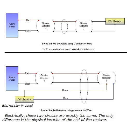
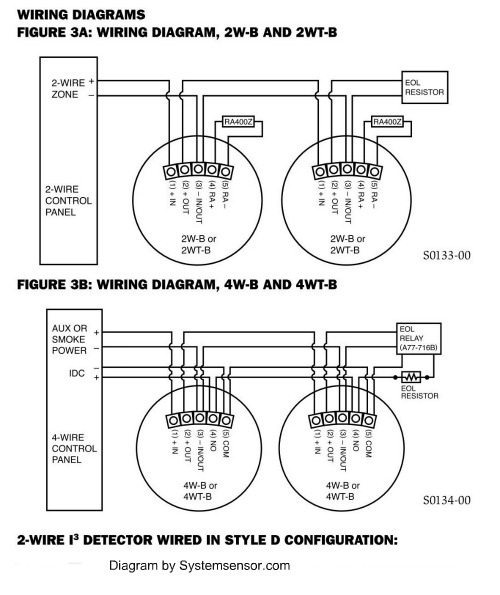
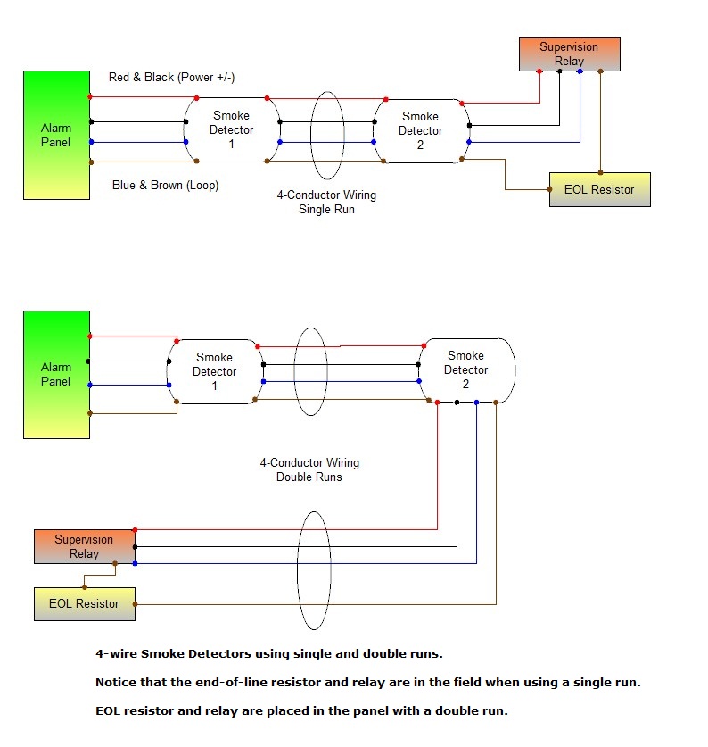
Smoke Detector Circuit Basics - Home Security Systems ... The System Sensor smoke detector circuits, shown below, are typical of most other manufacturers. The diagram shows the two basic types of smoke detectors, 2-wire and 4-wire. Most home alarm panels are designed to handle one type or the other, but some can handle both. Here's how they work: Two-wire Smoke Detector Circuit Types of Fire Alarm Systems and Their Wiring Diagrams A smoke or heat detector can be installed to the existing or new home wiring. in our basic wiring diagram, a single or multiple heat and smoke detectors are installed in the home by connecting the live (line or hot), neutral, ground and an interconnected wire to the alarm. The main supply is 120V AC (in US) and 230V AC (in EU). Flame, gas and smoke detector - Electronic Circuit Diagram The circuit diagram for gas detector and smoke detector separated in different circuit design diagram which can be downloaded from the provided link. All of schematic diagrams (flame detector, gas detector and smoke detector) are quite simple and easy to built. It uses 12V power supply to work, you may use batteries or accumulator or DC power ...
Smoke detector circuit diagram. Smoke Detector Wiring 101 | DoItYourself.com A hardwired smoke alarm installation involves wiring one of the smoke detectors (closest to the voltage source) to a 120 VAC breaker in the main electric panel or tapping from a 120 V electrical box, wiring it using a 14/2 cable with a black (live), a white (neutral), and a ground wire, as shown by the diagram in Figure 5. Smoke Detector using Gas Sensor - Arduino Project Hub CIRCUIT DIAGRAM Procedure 1.) Arrange the components as per the given circuit diagram 2.) Write the appropriate code for the requisite applications. 3.) Upload your code in the Arduino. 4.) Now simulate your circuit. Suggestions:- You may use other types of sensors You can replace the two LEDs by an RGB LED. Try to modify your code using functions. Circuit design Smoke Detector - 1710820 - Tinkercad Circuit design Smoke Detector - 1710820 created by Tanha Shamree with Tinkercad. Circuit design Smoke Detector - 1710820 created by Tanha Shamree with Tinkercad. Toggle navigation thingcover-properties. Smoke Detector - 1710820. 0 . thingcover-add_photo_of_thing_title. thingcover-valid_image_formats_size ... Interlinked Smoke Alarm Wiring Diagram - schematron.org Interlinked Smoke Alarm Wiring Diagram. How to install an interconnected mains operated smoke alarm. As its interconnected there is more than one but they were all done like this one. A hard-wired smoke or carbon monoxide (CO) alarm is wired to a V household electrical circuit and is connected to other detectors throughout your home.
Simple Smoke Detector Alarm Circuit using MQ02 The following prototype is a test circuit and it can be constructed through breakout board and PCB after calibration of each components. This smoke detector circuit will produce visible and audible alert when smoke detected. Circuit Diagram Components Required MQ-02 gas sensor IC LM358 Resistor 10KΩ, 100Ω Variable Resistor 10KΩ Capacitor 0.1µF LED Simple Smoke Detector Alarm Circuit Diagram Circuit Diagram of this Smoke Detector Project is given below: In this circuit, we have used an MQ2/MQ6 Smoke Or Gas Sensor Module for detect smoke present in the air. A BC547 NPN transistor is used to to drive buzzer whenever it detects smoke. A 10K pot is also used for calibration. Arduino gas sensor MQ2, Smoke Detector, Programming & Circuit A1 is the pin number and smokeS is the name of the A1. You can also give it any other name, even you can name it as l, m, n or x, y, z. but it's a good programming practice to use such a name which has a meaning. The name smokeS clearly shows that, with pin A1 of the Arduino or mega smoke sensor is connected. ionization smoke detector circuit diagram Archives ... Simple Smoke Detector Alarm circuit using MQ02 designed with few easily available components. Main part of…
Smoke Detector Alarm using MQ2 Sensor - Circuits DIY Circuit Diagram Working Explanation The operating voltage of this circuit is 5 to 12 volts DC and it is built around an LM358 op-amp IC. This IC is working here In a comparator mode. When the smoke is detected by the MQ2 smoke detector it will send a signal to the IC to activate it. This IC will activate the transistor. Wiring Diagram For Hardwired Smoke Detectors Installing a smoke detector circuit for a hardwired home security system. Using a fire alarm schematic to connect. A hard-wired smoke or carbon monoxide (CO) alarm is wired to a V household electrical circuit and is connected to other detectors throughout your home.How to Install a Hardwired Smoke Alarm. Hardwired Smoke Alarm Wiring Diagram. I replaced an old hardwired smoke detectors since the clips broke off to hold in in place. But when the electric was turned back on, all the other smoke ... Smoke Detector using MQ2 Gas Sensor and ... - Circuit Digest Smoke Detectors are very useful in detecting smoke or fire in buildings, and so are the important safety parameters. In this DIY session, we are going to build a Smoke Detector Circuit which not only sense the smoke in the air but also reads and displays the level of Smoke in the Air in PPM (parts per million). This circuit triggers the Buzzer when Smoke level becomes higher than 1000 ppm ... Smoke Detector System Using MQ2 Gas Sensor and Arduino ... Smoke Detector System Using Arduino and MQ2 Gas Sensor Circuit Diagram Working Principle of Smoke Detector System Using MQ2 Gas Sensor and Arduino When we turn on the system's power supply, at the same time the MQ2 gas sensor starts to sense the smoke level in the air and it gives the output value to the Arduino.
How to Build a Smoke Detector - Explained Through ... A very simple to build smoke detector circuit has been discussed here through a schematic diagram, which can be easily built and installed over an area for the necessary detection purposes. The circuit incorporates the versatile FIGARO TGS 813 gas sensor as the main sensing device. The detections made by the sensor is translated into a logic status through a comparator stage composed of the IC ...
Smoke Detector Circuit - ElectroSchematics.com The simple schematic diagram of a smoke detector presented here utilizes the gas sensor TGS 813 as the main detecting component. The circuit is pretty easy to build and performs useful fire hazard detection once installed into a possible fire prone zone. IC1 = 741 IC2 = 7805 T1 = TIP122 741 datasheet Buy assembled smoke detectors
Simple Smoke Detector Alarm Circuit MQ2/MQ6 Smoke Detector Circuit Working on this smoke detector alarm circuit is easy. In this article, we used the transistor operating properties to work with this circuit as a smoke detector. BC547 NPN transistor will turn on whenever it gets at least 0.70v at its base terminal. We, therefore, applied a voltage divider circuit at its base.
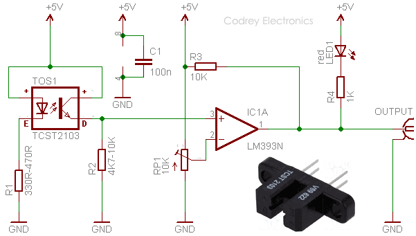
Simple Smoke Detector | Detailed Circuit Diagram Available Simple smoke detector circuit The photo-interrupter module ( H21A1 ) consists of a gallium-arsenide infrared LED coupled to a silicon phototransistor in a plastic housing. The slot (gap) between the infrared diode and the transistor (see Fig. 1) allows interruption of the signal with smoke, switching the module output from 'on' to 'off' state.
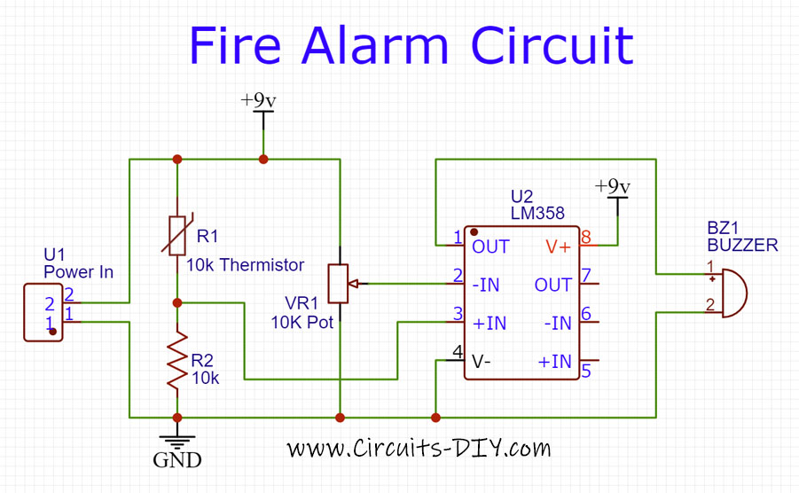
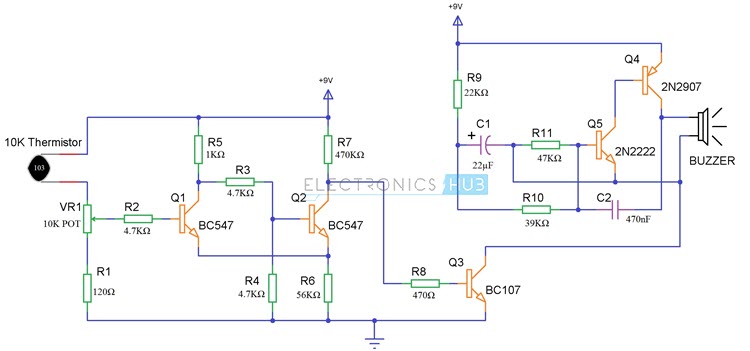
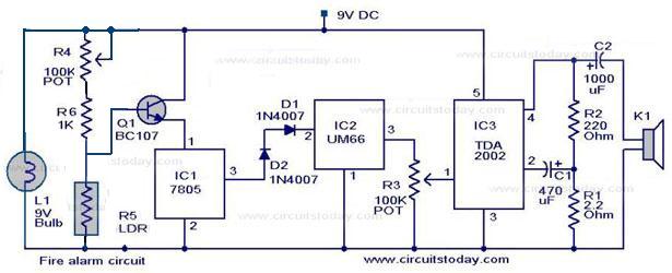
Fire and Smoke Detector System Project | Fire Alarm Diagram Fire alarm diagram / Circuit Working of Fire detecting alarm project Results 01. Fire and smoke detector System To detect the fire and turning on the alarm. The output of the fire and smoke detector system is the buzzer when ever the thermistor detects heat and temperature of fire the buzzer will turn on. 02. Required Components 03.
Simple Smoke Detector Circuit - Making Easy Circuits The following diagram in Figure 1.0 is the circuit diagram of our project: How it works? Building a smoke detector is cheap, yet very much effective. To develop the system, we have used LM358 comparator is used beside the MQ-2 smoke sensor. Here the LM358's inverted terminal is interfaced with POT to so as to adjust the sensitivity of the circuit.
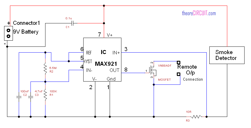
Remote Alarm For Smoke Detector Circuit Diagram Remote Alarm For Smoke Detector This alarm circuit was designed to monitor a mains-powered smoke detector located in a shed (which is used to house dog kennels). It provides complete isolation from the mains so that low-voltage (12V) cabling could be run to the alarm circuit which is located inside the house.
Make Your Own Smoke Detector Circuit Using Arduino : 8 ... Step 3: MQ2 Smoke Detector Arduino Shield Circuit: In this Smoke Detector Circuit with Arduino, we have used a MQ2 Gas Sensor to detect preset smoke in the air. A 16x2 LCD is used for displaying the PPM value of Smoke. And an LM358 IC for converting smoke sensor output into digital form (this function is optional).
Optical Smoke Detector | Detailed Circuit Diagram Available This optical smoke detector uses a low-cost, readily-available, slotted, through-scan, infrared photo-switch. When smoke is detected, the relay energises to activate the audio/visual warning alarm. Optical smoke detector. Fig. 1 shows the circuit of the smoke detector, while Fig. 2 shows pin configurations of sensor H21A1 and transistor BC547.
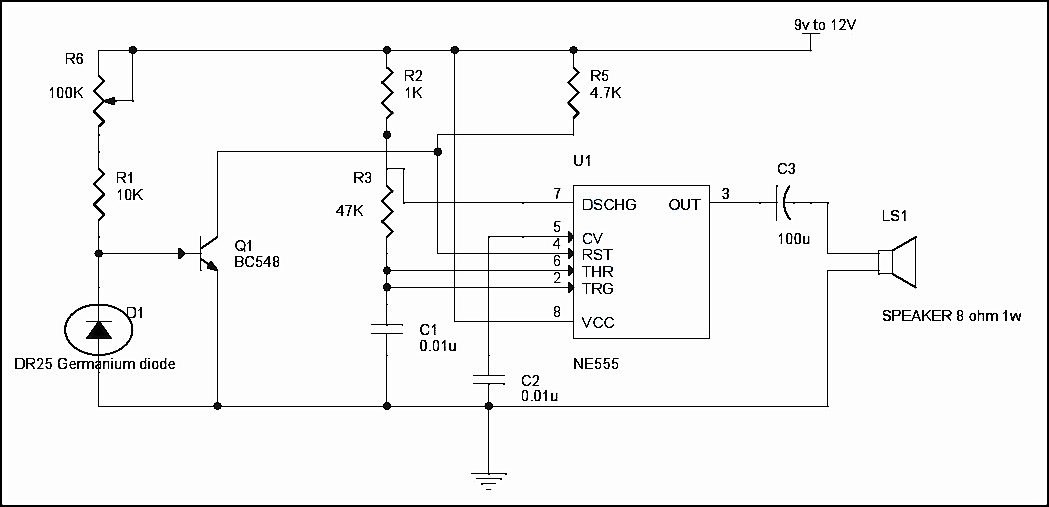
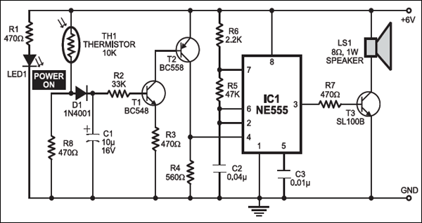
555 Timer based Smoke Detector Circuit Diagram ... - ElProCus 555 Timer-based Smoke Detector Circuit. Here is a simple smoke detector circuit using a 555 timer. This circuit is used to notice smoke and generate an alarm when the air is polluted. The circuit uses a 555 timer and sensor and the sensor module activates the oscillator and produces an alarm through the loudspeaker.
› publication › 275208316(PDF) 270 MINI ELECTRONICS PROJECT WITH CIRCUIT DIAGRAM Apr 20, 2015 · circuit diagram help from this book. Give your feedback by mailing me. ... Simple Smoke Detector 82. 140. Remote Emergency Alarm for Unmanned Lifts 83. 141. Audio-Controlled Running Light 84.
Photoelectric Smoke Detector - ElectroSchematics.com This photoelectric smoke detector circuit uses one LED and 2 LDRs to detect the smoke and sound an alarm. The LM1801 IC is the best choice for this circuit because we need a few external components and is used in almost any smoke alarm. The whole photoelectric smoke detector circuit is powered from the 220V mains supply.
Flame, gas and smoke detector - Electronic Circuit Diagram The circuit diagram for gas detector and smoke detector separated in different circuit design diagram which can be downloaded from the provided link. All of schematic diagrams (flame detector, gas detector and smoke detector) are quite simple and easy to built. It uses 12V power supply to work, you may use batteries or accumulator or DC power ...
Types of Fire Alarm Systems and Their Wiring Diagrams A smoke or heat detector can be installed to the existing or new home wiring. in our basic wiring diagram, a single or multiple heat and smoke detectors are installed in the home by connecting the live (line or hot), neutral, ground and an interconnected wire to the alarm. The main supply is 120V AC (in US) and 230V AC (in EU).
Smoke Detector Circuit Basics - Home Security Systems ... The System Sensor smoke detector circuits, shown below, are typical of most other manufacturers. The diagram shows the two basic types of smoke detectors, 2-wire and 4-wire. Most home alarm panels are designed to handle one type or the other, but some can handle both. Here's how they work: Two-wire Smoke Detector Circuit














Comments
Post a Comment