39 refrigeration cycle ph diagram
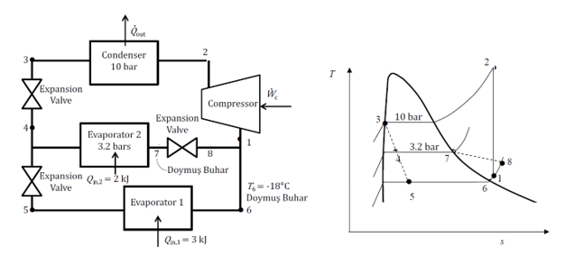
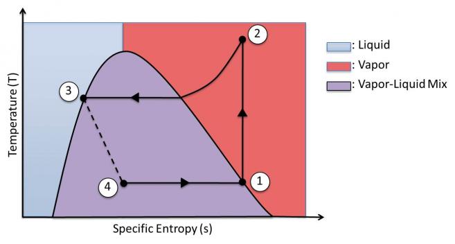
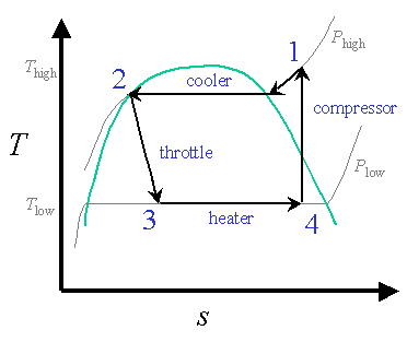
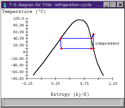
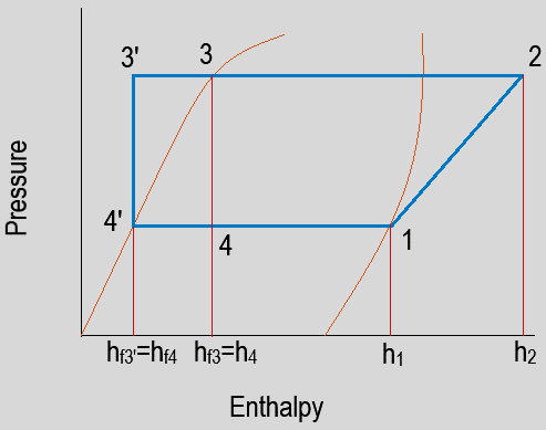
Refrigeration Cycle T-S & p-h Diagram The refrigerant cycle is described by the T-S & p-h diagram. Refrigeration cycle diagrams . COP of Refrigeration Cycle. The efficiency of the refrigeration cycle is described by COP or coefficient of performance. h1 = Sp. enthalpy before compression at Point 1; 20 Mar 2018 — When you can draw a refrigeration cycle on a p-h diagram, you can easily obtain the refrigerant characteristics through the diagram.
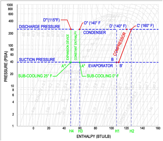
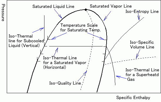
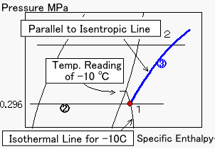
In general, a log p-h diagram shows the aggregate state of a substance, depending on pressure and heat. For refrigeration, the diagram is reduced to the relevant regions of liquid and gaseous as well as their mixed form. The vertical axis shows the logarithmic pressure and the horizontal axis shows the specific c enthalpy with linear scaling. Accordingly, the isobars are horizontal and the isoenthalps are vertical. The logarithmic scaling makes it possible to represent processes with large pressure differences. The saturated vapor curve and the boiling point curve meet at the critical point K. • pressure p • specific enthalpy h • temperature T • specific volume v • specific entropy s • gas content x
Refrigeration cycle ph diagram
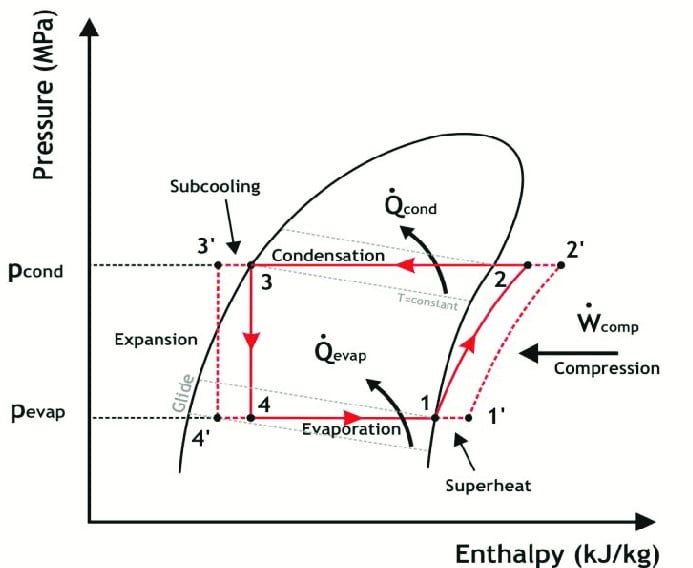
Refrigeration handbook 1. Basic heat transfer 2. Compression cycle 2.1 The pressure-enthalpy diagram; 2.2 Basic components; 2.3 The basic cycle in a log Ph diagram; 2.4 The complex cycle in a log Ph diagram; 2.5 Other components; 3. Compressors 4. Expansion valves 5. Refrigerants 6. Evaporators 7. Condensers 8. If you are interested in learning how a refrigeration system works, it is helpful to understand from the Ph (Pressure Enthalpy) chart perspective. It makes our life much easier. This is how the refrigeration cycle diagram looks: Yeah, it seems complicated at first, but it will be easier to understand once I have explained the refrigeration ... Principles of Refrigeration MAE 554 Professor H. Ezzat Khalifa Syracuse University P-h Chart for R134a (SI Units) ... P-h Diagram for Real Vapor Compression Cycle ... P-h Diagram for 2-Stage VCC with Subcooler. 11 0.6 0.8 1.0 1.2 1.4 1.6 1.8 2.0 2.2 2.4-40 -30 -20 -10 0 10203040 50
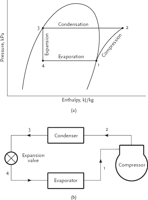
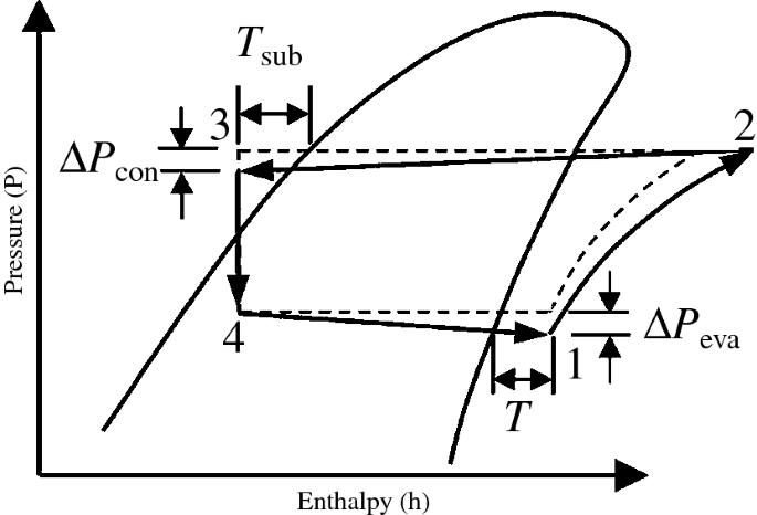
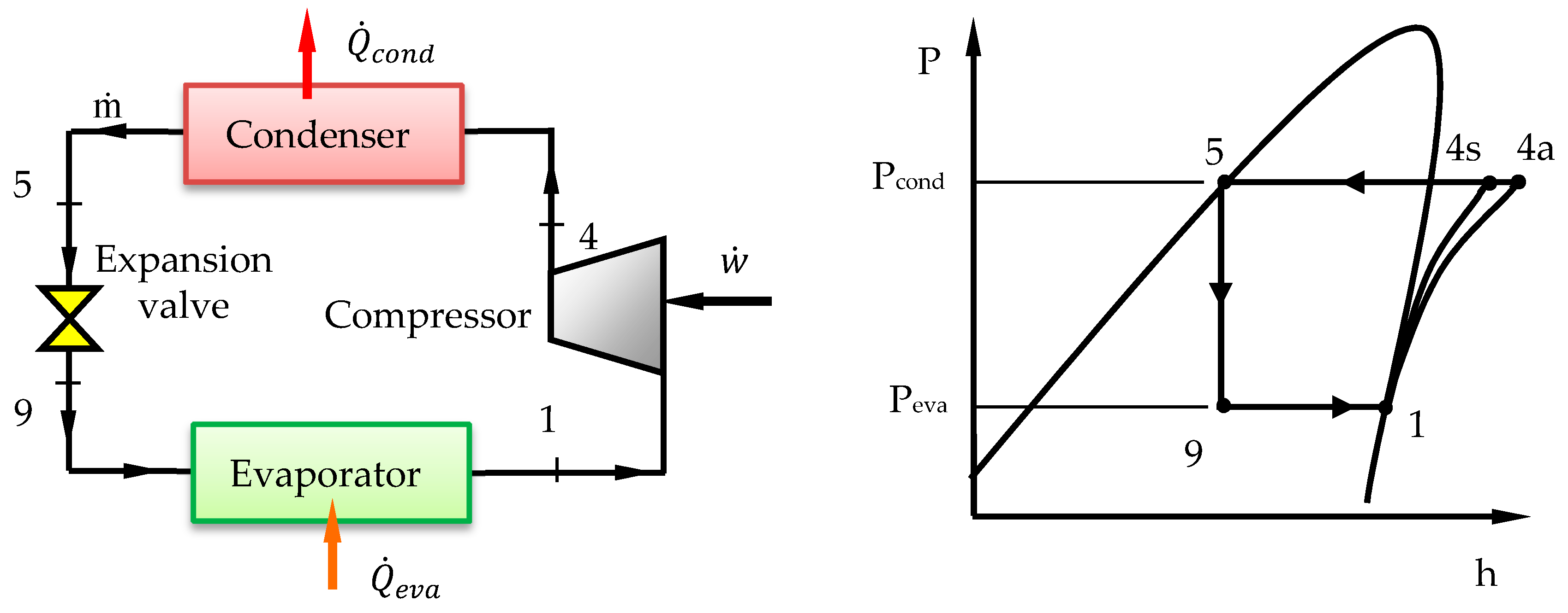
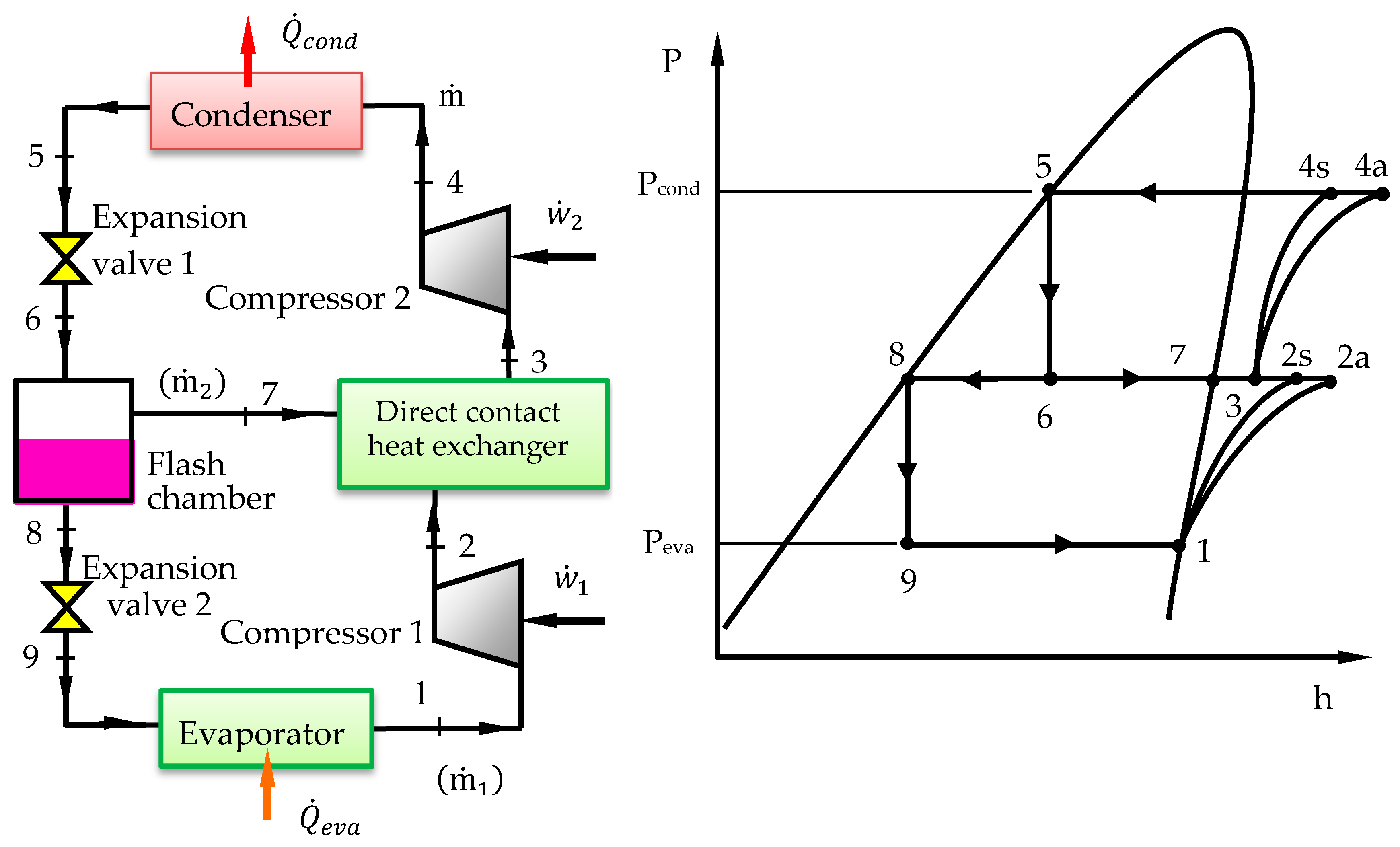
Refrigeration cycle ph diagram. M. Bahrami ENSC 461 (S 11) Refrigeration Cycle 3 Fig. 5-3: T-s and P-h diagrams for an ideal vapor-compression refrigeration cycle. 1-2: A reversible, adiabatic (isentropic) compression of the refrigerant. The saturated vapor at state 1 is superheated to state 2. wc =h2 − h1 Figure 1-6 Refrigeration Cycle P-H Diagram Image Figure 1-7 Properties of Refrigerant at -20℉ Figure 1-8 Properties of the Refrigerant at 105℉ H 1is the saturated suction of the compressor at -20ºF. at no losses. H 2is the compressor discharge point at no losses. H 5is the saturated liquid at 105ºF condensing temperature. The basic compressor-driven refrigeration cycle consists of one compressor, two heat exchangers (a condenser and an evaporator) and a throttling device ... the P-h diagram have been defined, the cycle can be plotted on a P-h chart. P-h charts for all common working fluids (refrigerants) are available. In these charts the pressure and enthalpy values are shown to scale. In the old days large charts were used, and refrigeration engineers would plot the circuit diagram on the chart, allowing various
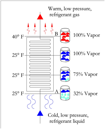
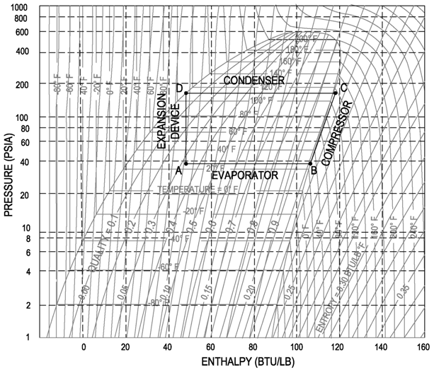
The refrigeration cycles can also be represented in a P-H diagram. Figure 5: P-H diagram representation of a dry refrigeration cycle Refrigerant fluid choice: We now turn our attention to the fluids. Usually, one tends to pick pL as low as possible, but not below atmospheric pressure. Thus, the refrigerant chosen needs to have a normal boiling ... It is recommended that the engineer get a copy of the P-H diagram for R-134a and the other common refrigerants. These diagrams can be found in the ASHRAE Fundamentals book. A sample R-134a diagram is shown below, with a sample refrigeration cycle, identifying (Step 1) Evaporator, (Step 2) Compressor, (Step 3) Condenser and (Step 4) Expansion ... The Refrigeration Cycle – Complete: In this final diagram of the refrigeration cycle we have introduced 3 new terms: Superheated, Saturated & subcooled. SUPERHEAT – Is an amount of heat added to refrigerant vapour beyond its boiling point. This ensures the refrigerant is in a gas state with no liquid present. Principles of Refrigeration MAE 554 Professor H. Ezzat Khalifa Syracuse University P-h Chart for R134a (SI Units) ... P-h Diagram for Real Vapor Compression Cycle ... P-h Diagram for 2-Stage VCC with Subcooler. 11 0.6 0.8 1.0 1.2 1.4 1.6 1.8 2.0 2.2 2.4-40 -30 -20 -10 0 10203040 50
If you are interested in learning how a refrigeration system works, it is helpful to understand from the Ph (Pressure Enthalpy) chart perspective. It makes our life much easier. This is how the refrigeration cycle diagram looks: Yeah, it seems complicated at first, but it will be easier to understand once I have explained the refrigeration ... Refrigeration handbook 1. Basic heat transfer 2. Compression cycle 2.1 The pressure-enthalpy diagram; 2.2 Basic components; 2.3 The basic cycle in a log Ph diagram; 2.4 The complex cycle in a log Ph diagram; 2.5 Other components; 3. Compressors 4. Expansion valves 5. Refrigerants 6. Evaporators 7. Condensers 8.
















Comments
Post a Comment