40 hvac wiring diagram pdf
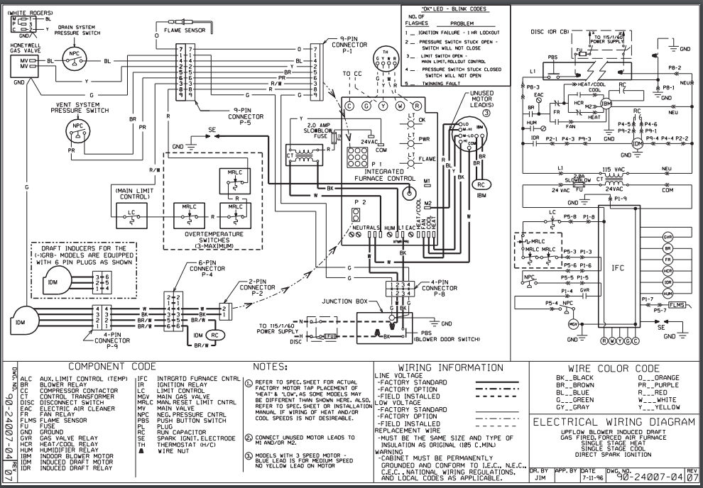
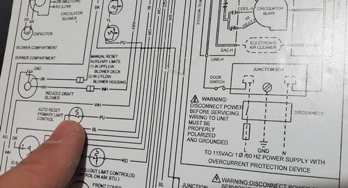
PDF WIRING DIAGRAM - Nortek Global HVAC Field Wiring Factory Wiring: Low Voltage High Voltage If any of the original wire as supplied with the furnace must be replaced, it must be replaced with wiring material having a temperature rating of at least 105 C. For Models G(3,4)R(-) Gas Furnaces with UTEC Control Board #624631 703799A (Replaces 7037990) R Y G W ROOM THERMOSTAT AIR CONDITIONER PDF Home Hvac Wiring Diagram - stats.ijm.org Understanding Electricity and Wiring Diagrams for HVAC/R Robert Chatenever 2000 This book provides HVAC/R service technicians with exceptionally practical information on the unique wiring diagrams, methods, technician short- cuts, and potential pitfalls encountered on the job.
PDF WIRING DIAGRAMS - Carrier PLUG 2 1・・CHEMATIC DIAGRAM 1. Use Copper Wire (75ツコc Min) Only Between Disconnect Switch And Unit. 2. To Be Wired InAccordance With N.E.C.And Local Codes. 3. IfAny Of The Original Wire,As Supplied, Must Be Replaced, Use The Same Or Equivalent Type Wire. 4. RedWire/WhiteStripeToQC1A,BLKWire/WhiteStripeToQC2A. 5.

Hvac wiring diagram pdf
PDF Fundamentals of HVAC Control Systems - Semantic Scholar Symbols for HVAC system components Refer to ASHRAE Fundamentals Handbook 2005 Chp. 37, Abbreviations and Symbols Refer to other local standards or guidelines Usually specified in the contract drawings & documents Generic control diagrams Using generic symbols to describe and define the requirements of the control system PDF SS103 Electrical Fundamentals v2 - LennoxPROs.com These magnets break the lines of force within the coils of wire and induce alternating current (AC) to be produced. This method of electrical generation is what powers our homes, our offices, and the heating and air conditioning equipment that maintains our comfort. HVAC Essentials Series Electrical Fundamentals Course SS103 PDF ParT 1 The Ins and Outs of Basic SchemaTIc SymBOlS - RSES The first and most commonly used is the crossover of two wires or lines, where they may cross or pass-over another line (1). It is very easy to confuse this format, due to the similarity in the simple connection shown in Figure 4 (4). The second is a half loop that seems to jump over the line as is being de- picted in Figure 5 (2).
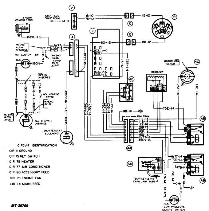
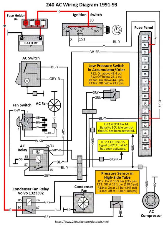
Hvac wiring diagram pdf. PDF Wiring diagrams - Pacific Ventilation ©Pacific HVAC Engineering 2016 Tel. Australia 1300 733 833 NZ 0800 100 326 Product Series Associated Wiring Diagrams PDF UNDERSTANDING ELECTRICAL SCHEMATICS Part 1 (Revised ... There are three basic types of wiring diagrams used in the HVAC/R industrytoday. The first and most common is the ladderdiagram, so called because it looks like the symbols that are used to represent the components in the system have been placed on the rungs of a ladder. hvac wiring diagram symbols pdf - Wiring Diagram and ... Schematic Diagrams For Hvac Systems Modernize Electrical Symbols For Other Pilot Devices Mechanical Drawing Symbols Design Elements Hvac Equipment Building Softe For Registers Drills And Diffusers Symbol Of Air Condition In A Circuit Components Symbols And Circuitry Of Air Conditioning Wiring Diagrams Part 2 York Air Conditioning Wiring Schematics Pdf - IOT Wiring ... York Air Conditioning Wiring Schematics Pdf. Figure 1 7 air conditioner wiring diagram sheet of 3 installation and service manuals for heating heat pump conditioning equipment brands t z free manual s troubleshooting challenge assisting with a split system problem 2018 07 09 achrnews achr news york r 410a technical pdf manualslib set fan sd ...
Wiring Diagrams - Honeywell Home Heating Controls Our Wiring Diagrams section details a selection of key wiring diagrams focused around typical Sundial S and Y Plans. Wiring Diagrams. Contains all the essential Wiring Diagrams across our range of heating controls. Click the icon or the document title to download the pdf. DOWNLOADS. Heating Controls Wiring Guide Issue 17. Terms & Conditions ... PDF Standard AC Wiring Diagrams update - Alpine Home Air This diagram is to be used as reference for the low voltage control wiring of your heating and AC system. Always refer to your thermostat or equipment installation guides to verify proper wiring. NOTESome AC Systems will have a blue wire with a pink stripe in place of the yellow or Y wire. 1(800) 865-5931 Understand Basic HVAC Electrical Components & Wiring in ... Connecting all of the electrical components together is the electric wiring. To keep track of wiring, HVAC technicians rely on circuit schematics or visual representations of wiring programs. There are three basic types of circuit schematics used in HVAC today. They are the Line Diagram, the Ladder Diagram, and the Installation Diagram. PDF WIRING DIAGRAM MANUAL Split System Air Conditioner Wire Diagram 340086-101 All R4A3, All R4A4, except R4A424(A,G)KA, All R4A5 except R4A518(A,G)KA & R4A524(A,G)KA, All WCA3, All WCA4 except WCA4244GKA, All WCA5 except WCA5184GKA & WCA5244GKA Wire Diagram 342878-101 N4A648GKB, N4A660GKB WARNING
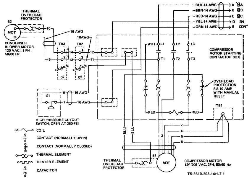
PDF WIRING DIAGRAM - Nortek Global HVAC WIRING DIAGRAM 7105290 (Replaces 7103220) 08/05 ¢7105292¤ 24 Volt Field Connection Comp Status LED Status LED Description Green "POWER" Module has power Red "TRIP" Thermostat demand signal Y1 is present, but the compressor is not running Yellow "ALERT" Flash Code 1 Long Run Time Compressor is running extremely long run cycle Wiring Diagrams | Bard Manufacturing - Bard HVAC The links below are to current Bard product wiring diagrams. All documents are in PDF format and will require Acrobat Reader. If you do not have this software on your system you can obtain a free download here: download Adobe Reader. To determine wiring diagrams specific to your product refer to the 2110 product parts manual. PDF Wiring Diagrams - Air Conditioning Fig. 2 - Wiring Diagram — Model size 2--1/2 -- 5 tons, 208/230--3 and Model size 3 -- 5 tons, 460/3. 3 NOTES: 1. Symbols are electrical representation only. 2. Compressor and fan motor furnished with inherent thermal protection. 3. To be wired in accordance with National Electric PDF HVAC Fundamentals - serviceteamtraining •Typically 24 volts is the operating voltage for HVAC controls. •240 volts is delivered to a _____, there it is stepped down to 24 volts A/C •After that, one common wire is connected to one side of the coil on all of the controls. •The _____determines which wires will complete a circuit while delivering 24 volts to a relay,
Hvac Schematic Symbols Pdf - Wiring Diagram Line Electrical Schematic Symbols Names And Identifications. Hvac Symbols. Electrical Clipart Hvac Symbol For Integrated Circuit Chip Png Full Size 170731 Pinclipart. Typical Electrical Drawing Symbols And Conventions. Components Symbols And Circuitry Of Air Conditioning Wiring Diagrams Part 2. Basic Electrical Engineering For Hvac Engineers.
PDF Wiring Diagrams - Home Page for Carrier air conditioning ... Fig. 9 - Wiring Diagram -- GT Series with Auxiliary Heat. 10 Fig. 10 - Wiring Diagram -- GW Series 2 through 6 Ton Capacity. 11 Fig. 11 - Wiring Diagram -- GW Series 10 Ton Capacity. 12 OPERATION FAULT FLASH CODE FAULT FLASH CODE Standby 19-30 VAC power is present
PDF Heating Controls Wiring Guide Connect the controls, pump, boiler and 230 Volt fused supply to the junction box terminals indicated by the arrows in the diagrams next to each control, other electrical device or circuit. These diagrams should be read in conjunction with product installation instructions. A list of boilers can be found on page 16.
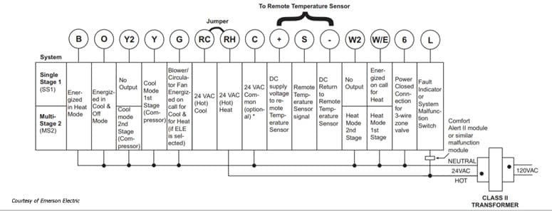
PDF Standard AC with Standard Furnace Control Wiring This diagram is to be used as reference for the low voltage control wiring of your heating and AC system. Always refer to your thermostat or equipment installation guides to verify proper wiring. NOTESome AC Systems will have a blue wire with a pink stripe in place of the yellow or Y wire. 1(800) 865-5931
PDF Introduction: Hvac Basics Starting at point A on the diagram above, return air passes through the filters on the system and is drawn into the supply fan. The air is then pushed into the dual duct section of the unit. It will now separate into two ducts, one that will handle the heating functions and one that will handle the cooling functions:
PDF Practical Exercise Wiring HVAC Circuits - JustAnswer Welcome to the Wiring HVAC Circuitspractical exercise! As you know, HVAC stands for heating, ventilation, and air conditioning. This exercise includes topics related to HVAC systems and incorporates material presented in the Electric Heating, Controls for Air Conditioning, and Reading Electrical Schematic Diagrams study units. The purpose of ...
hvac wiring diagram symbols pdf - IOT Wiring Diagram Typical Electrical Drawing Symbols And Conventions. Hvacr symbols hvac electrical wiring legend mechanical drawing design pdf schematic diagrams for systems other pilot devices air conditioning appendix iii general how to construct names analog and digital typical controls ladder diagram explained read gray furnaceman ford truck technical drawings a plc at cooled split type ac unit software ...
PDF Carrier Hvac Wiring Diagram - stats.ijm.org carrier-hvac-wiring-diagram 1/2 Downloaded from stats.ijm.org on April 5, 2022 by guest Carrier Hvac Wiring Diagram When people should go to the books stores, search opening by shop, shelf by shelf, it is truly problematic.
PDF HVAC Electrical Wiring Diagrams / Ohm's Law / Sequence of ... HVAC Electrical - Wiring Diagrams / Ohm's Law / Sequence of Operation RV 6.8.20 2 7. In a balanced charge _____. the electrons weigh the same as the protons the protons weigh the same as the neutrons 4. the protons and the neutrons weigh the same amount the number of electrons equals the number of protons 8.
PDF ParT 1 The Ins and Outs of Basic SchemaTIc SymBOlS - RSES The first and most commonly used is the crossover of two wires or lines, where they may cross or pass-over another line (1). It is very easy to confuse this format, due to the similarity in the simple connection shown in Figure 4 (4). The second is a half loop that seems to jump over the line as is being de- picted in Figure 5 (2).
PDF SS103 Electrical Fundamentals v2 - LennoxPROs.com These magnets break the lines of force within the coils of wire and induce alternating current (AC) to be produced. This method of electrical generation is what powers our homes, our offices, and the heating and air conditioning equipment that maintains our comfort. HVAC Essentials Series Electrical Fundamentals Course SS103
PDF Fundamentals of HVAC Control Systems - Semantic Scholar Symbols for HVAC system components Refer to ASHRAE Fundamentals Handbook 2005 Chp. 37, Abbreviations and Symbols Refer to other local standards or guidelines Usually specified in the contract drawings & documents Generic control diagrams Using generic symbols to describe and define the requirements of the control system















Comments
Post a Comment