39 inverter wiring diagram manual
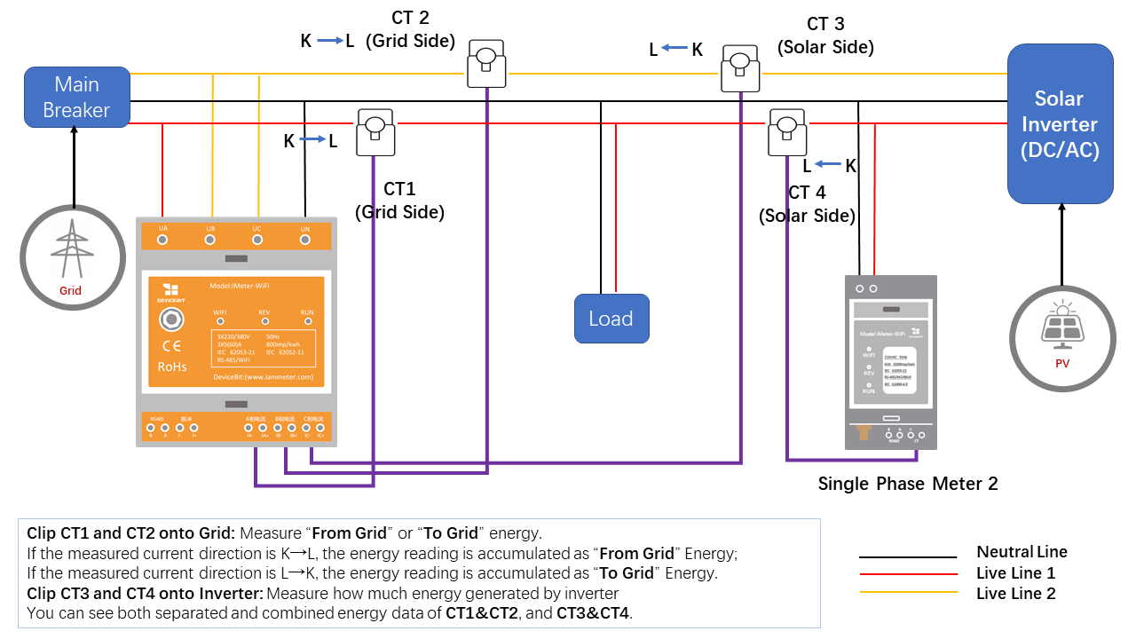
PDF Deye-Inverters-manual ...3.9 Wiring System for Inverter 3.10 Single phase parallel connection diagram 3.11 Split phase · This chapter contains important safety and operating instructions. Read and keep this manual for future · Before using the inverter, please read the instructions and warning signs of the battery and... PDF EN / ACS880-107 inverter units hardware manual The diagram below shows the default I/O connections on the inverter control unit (A41), and describes the use of the connections in the inverter unit. Under normal circumstances, the factory-made wiring should not be changed. The wire size accepted by all screw terminals (for both stranded and solid...
Simple 100W Inverter Circuit - Working and Circuit Diagram [UPDATED] Here is the circuit diagram of a simple 100-watt inverter using IC CD4047 and MOSFET IRF540. The circuit is simple low cost and can be even assembled on a Here it is wired as an astable multivibrator producing two pulse trains of 0.01s which are 180 degrees out of phase at the pins 10 and 11 of the IC.

Inverter wiring diagram manual
PDF L510 Inverter Read this Instruction Manual thoroughly before proceeding with installation, connections (wiring) It is essential to verify the L510 inverter nameplate and make sure that the L510 inverter has the Middle Snap hook. Din Rail Mounting & Dismounting as shown in the diagram below:-Use a 35mm Din Rail. Wiring Diagram Of An Inverter - Schematic Diagram Images Wiring diagram for inverter fresh exelent rv electrical wiring. Inverter wiring correct inverter wiring in a battery based pv system abstract. Ups inverter wiring diagram with auto manual changeover switch system. Check out my other video on how to weld with 3 car batteries. PDF 4 Wiring Of Frequency Inverter .17... Wiring Of Frequency Inverter 23. 4.4.2 Main loop terminal diagram. Energy consum能pti耗on制br动aki电ng阻resistor. Figure 4-2 Basic Wiring Diagram of V350 Series Inverters. V350 Low-Power Closed-Loop Vector Inverter User Manual.
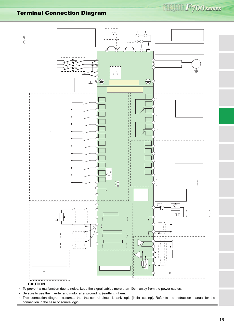
Inverter wiring diagram manual. PDF CHF Series Universal Inverter Operation Manual 10 Wiring diagram. Notice: z Inverters between 18.5KW and 90KW have built-in DC reactor which is used. 4.5.2 Wiring at inverter side of main circuit 4.5.2.1 DC reactor Inverters from 18.5kW to 90kW have built-in DC reactor which can improve the power factor, 4.5.2.2 Braking unit and braking resistor. This manual will be helpful in the installation, parameter setting, troubleshooting, and daily maintenance of the AC motor drives. shows main circuit shows control circuit. Fig.3-3 Basic Wiring Diagram. NoteBreaking resistor terminals BR+/BR- for the inverter of 15KW or below. PDF FREQROL-CS80 Instruction manual (detailed) 8.3.1 Inverter outline dimension drawings. Revisions. Inverter FREQROL-CS80 instruction manual (detailed). FR-CS84-012 to 295 2. installation and wiring. 2.4 Terminal connection diagrams. *1 The signal assigned to each of these terminals can be changed to the reset... RV Electrical Diagram (Wiring Schematic) | Converters vs. Inverters View our RV wiring Diagram to understand how an RV electrical system works and the diference between AC and DC Converters vs. Inverters. DC is for Priorities - AC is for the Extras. Sources of RV Power. Many manuals advise using the generator instead of the alternator whenever possible.
Basic Inverter - Schematic Design | Electronic Circuit Diagram The following diagram is the basic design diagram of inverter circuit. The circuit will convert 12V DC to 120V AC. This basic inverter circuit can handle up to. Wire, Case, Receptical (For Output). Notes: 1. Q1 and Q2, as well as T1, determine how much wattage the inverter can supply. PDF Microsoft Word - 封面封底.doc | 2 Type and specification of the inverter Universal inverter Ver.4.0. Service manual. Shenzhen encom electric technologies co.,ltd. Print version:V4.0-A5. 3.4.1 Connection between inverter and fitting parts 3.4.2 Main loop terminal wiring 3.5 Basic running wiring diagram 3.6 Control loop collocation and wiring 3.6.1... PDF Operation Manual GD350 | 4.4.1 Wiring diagram of basic control circuit This operation manual presents installation wiring, parameter setup, fault diagnosis and trouble shooting, and precautions related to daily maintenance. Read through this manual carefully before installation to ensure Goodrive350 series inverter is installed and operated in a proper manner to give... PDF ED3300说明书 | Chapter3 Installation and Wiring of Inverter Wiring board. Diagram 1-3 Outline of inverter. 1.3 Safety attentions. l Check after having received product. Diagram 3-2 Installation of multi inverters. 3-1. GT210 series general purpose inverter instruction manual Diagram3-1 Installation space condition.
PDF Preface | MD320/MD320N User Manual This manual is a guide to the operations of MD series inverter and MD320 control module. For the use of MD300 control module, see If the user needs to use the inverter with the methods other than the recommended wiring diagram in this manual, such as shared DC bus, please consult our company. PDF 功能码 | Chapter 4 Running of Inverter YX3000 Senseless Vector Type Inverter Manual. may be bigger than 3.5mA, for safety's sake, this equipment and its associated motor must be well inverter should be connected to AC power through circuit breaker. (7) Please use twisted wire or shielded wire above 0.75mm for the wiring of relay. Fuling inverter DZB300 Series Manuals | ManualsLib Manuals and User Guides for Fuling Inverter DZB300 Series. Basic Wiring Diagram. 9. Main Circuit Terminals and Wiring. 9. Notes on Wiring. 10. Control Terminals and Wiring. 3.3 Inverter Wiring | Manualzz | User manual | 3.3 Inverter Wiring User manual | 3.3 Inverter Wiring. Table of Contents. 3.3 Inverter Wiring. 3.3.1 Wire Gauges and Tightening Torque. To comply with UL standards, use The following is the standard wiring diagram for the F510 inverter (◎ indicates main circuit terminals and ○ indicates control circuit terminals ).
PDF Electrical wiring diagram | B HOW TO USE THIS MANUAL WIRING DIAGRAM. Provides circuit diagrams showing the circuit connections. 2 prius (EM01R0U). How to use this manual b. Inverter C 5 Converter C 6 Converter C 7 Crankshaft Position Sensor C19 Coolant Heat Storage Tank Outlet Temp.
PDF E series Inverter Wiring Diagram Naming Rules 13 E series Inverter Wiring Diagram 14 E100/E102 series External. Dimension 17 E180 series External Dimension 18 EM60 series External Manual torque compensation (0.10%-30.0%); Automatic torque compensation Key-board, terminal, RS485 communication. 14 main sources, 14...
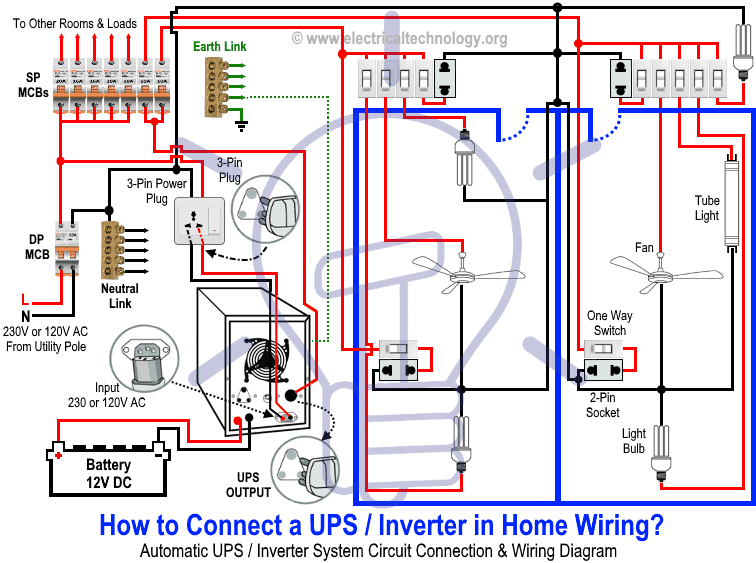
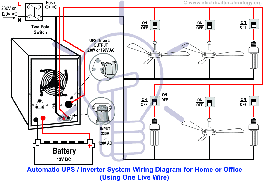
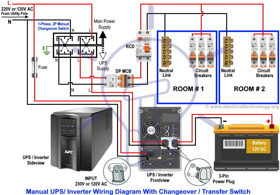
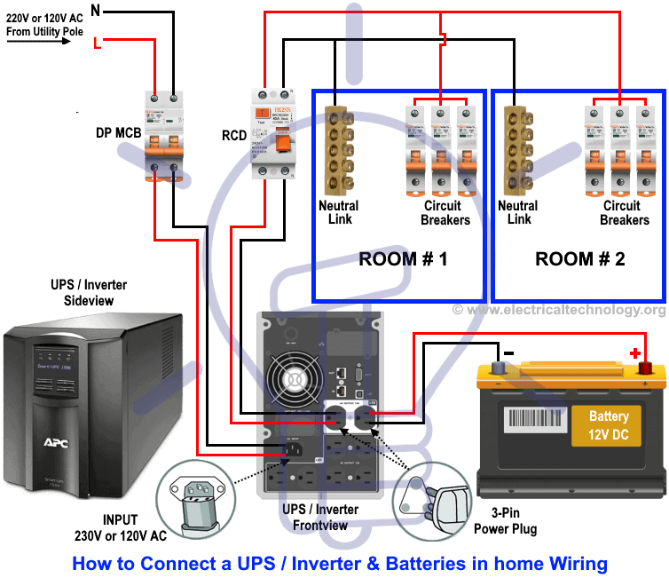
Automatic UPS / Inverter Wiring & Connection Diagram to the Home Automatic UPS Inverter System Wiring Diagram (One Live Wire). Working and Operation of UPS Connection. Read all the instructions, user manuals, cautions and follow them strictly. Doing your own electrical work is dangerous as well as illegal in some areas.Contact the licensed electrician or...
How to Design an Inverter - Theory and Tutorial - Homemade Circuit... The following manual simulation shows the basic operating principle of a center tap transformer based push pull inverter circuit. Here's the block diagram which illustrates how to implement the above elements with a simple configuration (center tap push-pull).
PDF 封面-封底-EN | E-series Inverter Wiring Diagram Naming Rules 09 E-series Inverter Wiring Diagram 10 E100/E102-series External. Dimensions 11 E180-series External Dimensions 12 EM60-series External Dimensions 13 Accessories 15 CDRA-series Full-digital Intelligent. Soft Starter for AC Motors 19 Energy-consumption Brake Unit and.
House Wiring & Inverter wiring Connection diagram - YouTube How to Connect an Inverter at Home ?. In this video, we explain how a house wiring is done along with USP/inverter single wire wiring connection.
Схемы Инверторов | Inverter48 INVERTER48. РЕМОНТ СВАРОЧНЫХ ИНВЕРТОРОВ тел.8-920-500-83-43. Главная.
PDF FR-S500 Instruction manual(basic) | 2.1 Installation of the Inverter Many of the diagrams and drawings in this instruction manual (basic) show the inverter without a cover, or partially open. Wrong wiring might lead to inverter damage. The control signal lines must be kept fully away from the main circuit to protect them from noise.
PDF N3 Operating Manual Inverter Wiring; Input Power Wiring 13. N3 Drive Operations Manual. 9.0 Input / Output Power Section Block Diagram. The following Fig. Refer to the parameter section of this manual and to General Wiring Diagrams 5.0 and 6.0 for further explanation of the functions and connections.
UPS / Power Inverter Wiring Diagram 3 Methods For Circuiting UPS & Inverter With Home & Office Wiring. Learn how to circuit UPS or Power Inverter with household appliances like fans, tube Method No. 1: Without connecting "output neutral" of UPS or Power Inverter with appliances and directly providing common neutral of home, apartment...
Delixi Inverter Manual - [PDF Document] Aside from operation instructions, this manual also presents some wiring diagrams for your reference. If you have any difficulty or special demands for using the inverter, please contact our offices or distributors. You may also contact the customer service centre of our head office for our quality service.
PDF 4 Wiring Of Frequency Inverter .17... Wiring Of Frequency Inverter 23. 4.4.2 Main loop terminal diagram. Energy consum能pti耗on制br动aki电ng阻resistor. Figure 4-2 Basic Wiring Diagram of V350 Series Inverters. V350 Low-Power Closed-Loop Vector Inverter User Manual.
Wiring Diagram Of An Inverter - Schematic Diagram Images Wiring diagram for inverter fresh exelent rv electrical wiring. Inverter wiring correct inverter wiring in a battery based pv system abstract. Ups inverter wiring diagram with auto manual changeover switch system. Check out my other video on how to weld with 3 car batteries.
PDF L510 Inverter Read this Instruction Manual thoroughly before proceeding with installation, connections (wiring) It is essential to verify the L510 inverter nameplate and make sure that the L510 inverter has the Middle Snap hook. Din Rail Mounting & Dismounting as shown in the diagram below:-Use a 35mm Din Rail.


















Comments
Post a Comment