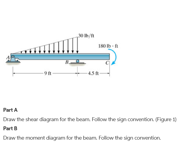
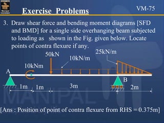
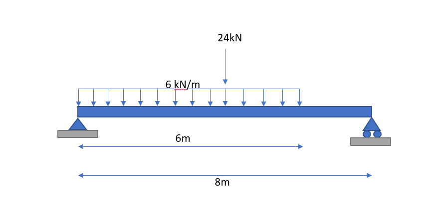
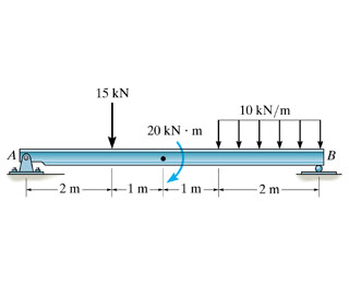
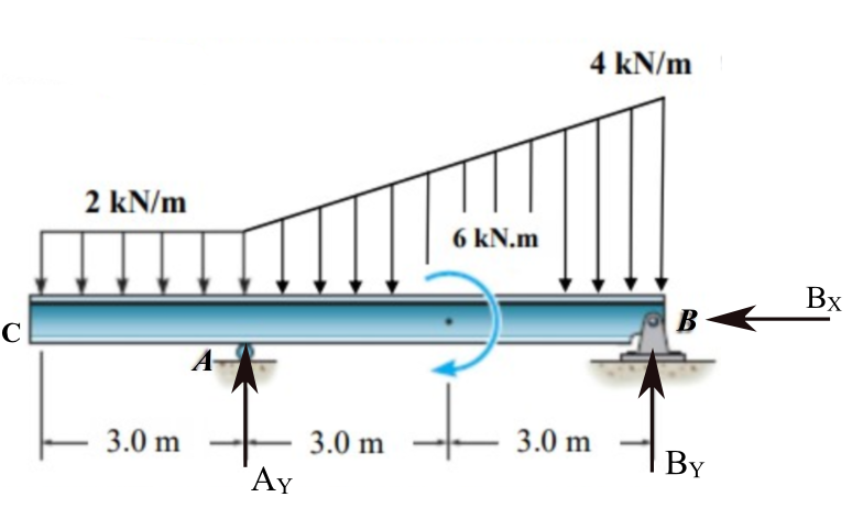
40 draw the shear diagram for the beam. follow the sign convention.
28.01.2021 ... 1 Answer to Draw the shear diagram for the beam. Follow the sign convention. (Figure 1) Draw the moment diagram for the beam. I think you will find this useful: New Doc 2019-04-12 17.41.20 https://www.camscanner.com/share/show?encrypt_id=MHgzZjUzNDEyOQ%3D%3D&sid=D440976A224841AERR7dy6S0 Shared using #CamScanner
Solution for Draw the shear diagram for the beam. Follow the sign convention. 6 kN 12 kN/m 6 m 3 m.

Draw the shear diagram for the beam. follow the sign convention.
Draw the shear-force and bending moment diagrams for a simply supported beam AB supporting a... Draw the shear-force and bending moment diagrams for a simply supported beam AB supporting a linearly varying load of maximum intensity 3 kN/m [Fig. 3.8 (a)]. Jan 28 2022 05:21 AM. Hello, hoping someone can explain why they calculate the bending moments of the beam by multiplying the UDL by the distance away from the left, and then by half of that distance again? i.e. 10 x 1 x 0.5, why not just 10 x 1? ​ https://preview.redd.it/wwf3w33bp7a21.png?width=609&format=png&auto=webp&s=6ee42fadcf2255609f2eadaeb79fe096f7b87c12 Solution for Draw the shear diagram for the beam. Follow the sign conventio 6 kN 12 kN/m 6 m 3 m. ... Follow the sign convention. 6 kN 12. fullscreenExpand.
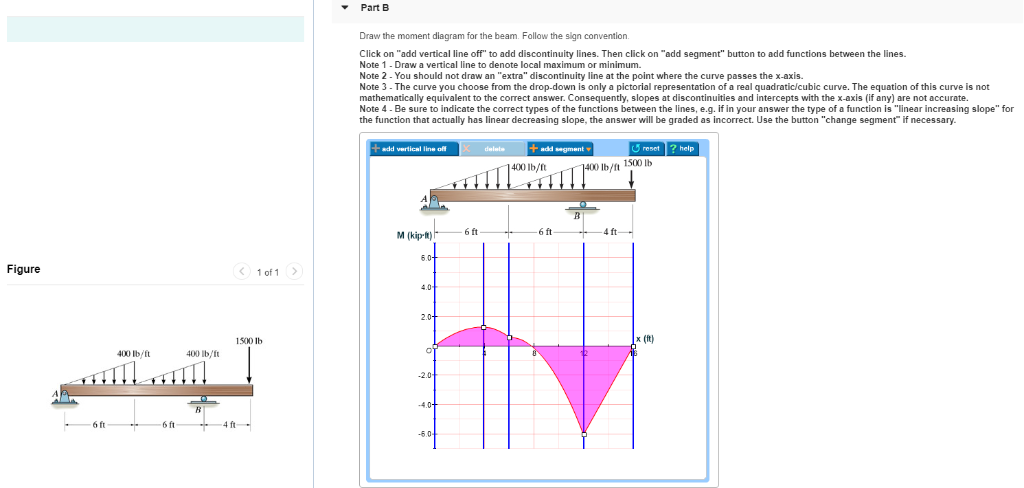
Draw the shear diagram for the beam. follow the sign convention.. 02.01.2022 ... Draw the moment diagram for the beam. Follow the sign convention. Click on "add vertical line off" to add discontinuity lines. Problem 7.59 Part A Draw the shear diagram for the beam. Follow the sign convention.(Figure 1) Part B Draw the moment diagram for the beam. Follow the signconvention. Draw the shear diagram for the beam follow the sign convention figure 1. basics of shear force and bending moment diagrams and sign conventions for shear force and bending moment in our recent posts. The moment diagram should indicate which portions are curved and which. 17.08.2018 ... When drawing the shear force and bending moment diagrams of a beam we use the following sign convention for the shear force and the bending ...
About The Moment Diagrams Beams Draw Shown Shear Below The And For . Step 2: Draw the Moment diagram, M. on the typical ILD's shown below to maximize the response functions? 37. Solved part a draw the shear diagram for the beam follow figu of part a draw the shear diagram for the beam. Question: Draw the shear and moment diagrams for the beam.Problem 7-61 from:Engineering Mechanics: Statics, 14th editionRussell C. Draw the shear and moment diagram for the beam and loading shown. As seen from f.1 (b), the positive sign convention is (a) tension axial Neglect the weight of the beam. A) calculate the shear force and bending moment for the beam subjected to a concentrated load as shown in the figure. (Figure 1) Part B Draw the moment diagram for the beam. Follow the sign convention. This problem has been solved! See the answer ...
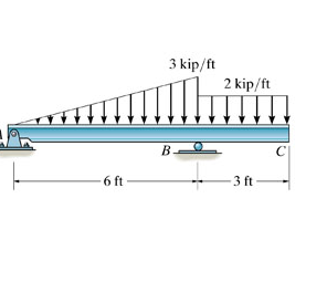
Hey guys, I'm a late-twenties ME who's reteaching myself my undergrad curriculum for the sake of technical interviews (ugh). Thanks bay area. Anyway, I'm rolling through my statics and I'm having a little problem with shear and moment diagrams. The concept is straight forward. I've no problem calculating the reaction forces. But when I'm drawing my shear diagram, cutting my beam from left to right, I struggle to figure out which direction to draw my shear. My 1960's statics textbook is good bu... Draw the moment diagram for the beam. Follow the sign convention. 3 kip/ft 2 kip/ft B с 6 ft 3 ft Draw the shear diagram for the beam. Follow the sign convention. (Figure 1) 1 answer The answer should be 0.02 m/s, please show how A downstream pump requires that particles passing through it be less than 0.15 mm in diameter. For a waste flow ... Problem 4. (Problem 5.15) For each beam, For each beam, draw the shear diagram draw moment diagram label the maximum values of shear and moment locate points of inflection make a sketch of the deflected shape Transcribed image text: Problem 7.59 Part A Draw the shear diagram for the beam. Follow the sign convention. (Figure 1) Click on "add vertical line off" to ...
Answer of Draw the shear diagram for the beam. Follow the sign convention. Draw the moment diagram for the beam. Follow the sign convention.
Shear Force Diagram S.F. at D, F D Draw the shear and moment diagrams for the beam loaded as shown. A beam is loaded as shown in fig. Problem 407 beam loaded as shown in fig. The simply supported beam in fig. Consider a simple beam shown of length l that carries a uniform load of w (n/m) throughout its length and is held in equilibrium by ...
Answer to: Draw the shear diagram for the beam in the figure. Follow the sign convention. By signing up, you'll get thousands of step-by-step...
This question came up when I was practicing martial arts. The master just referred to it as a "lever" effect (which I am not sure if it is accurate). Is it because of a lever effect? Or does it have to do with torque?
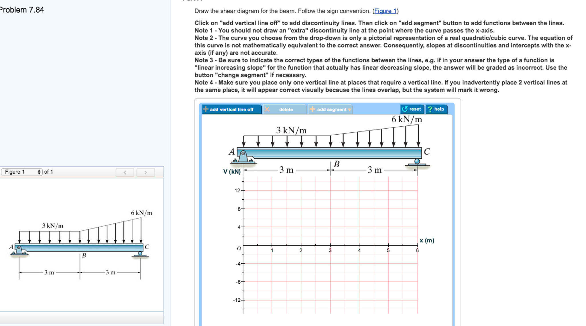
PART A Draw the shear diagram for the beam. Follow the sign convention. (Figure 1) Click on "add vertical line off" to add discontinuity lines. Then click on "add segment" button to add functions between the lines. Note 1 - You should not draw an "extra" discontinuity line at the point where the curve passes the x-axis.
The starter relay is a... 32 Draw The Shear Diagram For The Beam Follow The Sign Convention Install the reduce spring and the adjuster screw onto the base of the the new brake shoes securing both shoes together. Students need to understand the similarities and differences between Jews, Christians and Muslims to better prepare for our global ...
Draw the shear diagram for the beam. Follow the sign convention. (Figure 1). Click on "add vertical line off" to add discontinuity lines.
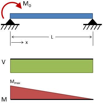
Once you have the reactions, draw your Free Body Diagram and Shear Force Diagram underneath the beam. Finally calculating the moments can be done in the following steps: 2. From left to right, make "cuts" before and after each reaction/load. To calculate the bending moment of a beam, we must work in the same way we did for the Shear Force ...
Step 2 of 3. (A) Draw the free body diagram of the section of the beam at the range as shown in Figure (3). Here, horizontal location on the beam with respect to point A is x and the maximum magnitude of distributed load at the x location is y. Determine expression for the maximum magnitude of distributed load ( y) using similar triangles rule ...
Follow the sign convention. UDL and UVL load. A uniformly distributed load (UDL) is a load that is distributed or ...
Solution for Draw the shear diagram for the beam. Follow the sign conventio 6 kN 12 kN/m 6 m 3 m. ... Follow the sign convention. 6 kN 12. fullscreenExpand.
Hello, hoping someone can explain why they calculate the bending moments of the beam by multiplying the UDL by the distance away from the left, and then by half of that distance again? i.e. 10 x 1 x 0.5, why not just 10 x 1? ​ https://preview.redd.it/wwf3w33bp7a21.png?width=609&format=png&auto=webp&s=6ee42fadcf2255609f2eadaeb79fe096f7b87c12
Draw the shear-force and bending moment diagrams for a simply supported beam AB supporting a... Draw the shear-force and bending moment diagrams for a simply supported beam AB supporting a linearly varying load of maximum intensity 3 kN/m [Fig. 3.8 (a)]. Jan 28 2022 05:21 AM.














Comments
Post a Comment