39 cpu circuit diagram
If site preparation or field wiring is necessary, you must refer to the following manual for installation instructions: 576013-879 TLS-3XX Series Consoles Site Prep and Installation Manual TLS-350 Series Sensor Module Installation Guide Safety Precautions Working of PC Fan Controller Circuit. In a normal PC or notebook PC, most of the heat generated is by the processor. This heat must be removed efficiently and quietly. A PC Fan along with a heat sink is an excellent active cooling system for computers. Most modern motherboards include a provision for on board CPU fan control.
Input / output wiring of different types of CPU Figure 1. Cpusr20 wiring diagram Figure 2. Cpusr40 wiring diagram Figure 3. Cpucr40 wiring diagram Figure 4. Cpust40 wiring diagram Figure 5. Cpusr60 wiring diagram Figure 6. Cpust60 wiring diagram Digital input wiring Figure 7. Drain input connection figure 8. Source input connection For most inputs, …

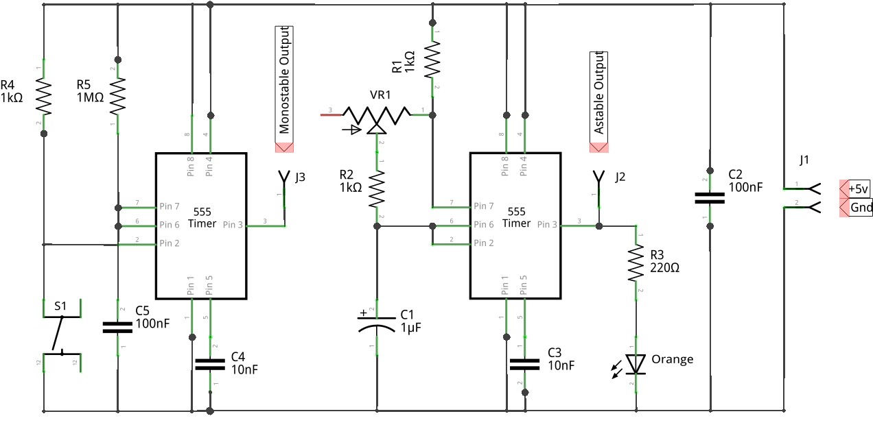
Cpu circuit diagram
The central processing unit (CPU) The CPU in modern computers is the embodiment of the "mill" in Babbage's difference engine. The term central processing unit originated way back in the mists of computer time when a single massive cabinet contained the circuitry required to interpret machine level program instructions and perform operations on ... This is a conceptual circuit diagram of the power train of a typical ATX computer power supply unit. This schematic does not show the control circuitry, that's why you see all MOSFET gates and transistor bases are open. For clarity, the parts responsible for miscellaneous auxiliary functions, such as current limit, fan control, and OV ... The tiny part of circuit in the OP seems pretty meaningless, it's not a 'simplified' processor, but merely a tiny part of one. For the OP - I would completely ignore the 'diagram', it's of no use to you (or anyone else), and presumably was only given to explain a small specific point.
Cpu circuit diagram. Circuit Diagram Of Smps Power Supply Fly-Back Converter. The unregulated input-voltage with a constant value is converted into a required output voltage by fast switching with the help of a 'MOSFET'; the switching frequency is around 100 kHz. The isolation of voltage can be achieved by means of a transformer. 1 mA Input delay (for rated value of input voltage). Wiring diagrams for Siemens NEMA contactors and starters. SIMATIC S7 S Programmable controller. CPU C wiring diagrams CPU C wiring diagrams Table 1 CPU C AC/DC/Relay (6ES7 BGXB0)1/5 (1). Hi, I am using the internal 24Vdc to supply all of my inputs and outputs. Wiring. Simatic S7 1200 Programmable Controller Cpu 1214c Wiring Diagrams 34m7ejv7jo46. 6es7212 1be40 0xb0 Siemens Simatic S7 1200 Cpu 1212c Plc City. 西門子s7 1200系列plc全套接線圖 很實用 每日頭條. S7 1200 Cm1231 Ai. Update To The S7 1200 System Manual Edition 09 2018. 西門子s7 1200系列plc全套接線圖 很實用 ... Download scientific diagram | Circuit diagram of the CPU structure. from publication: A microcontroller-based system for automated and continuous sky glow measurements with the use of digital ...
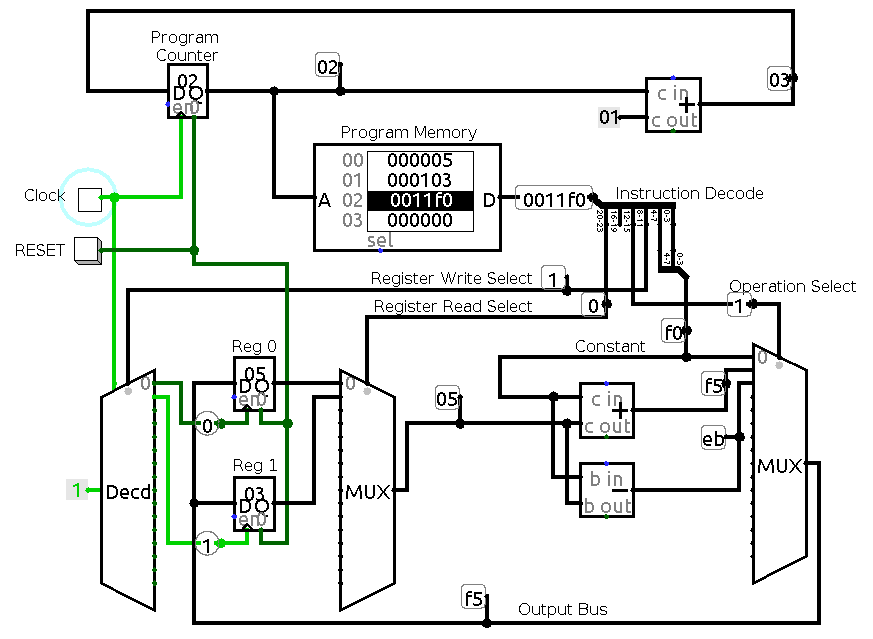
CPU Board. This schematic includes: LR35902, The main CPU (Commonly known as GB-Z80; with pinout) LH5264, 8192 byte work RAM (With pinout) LH5264, 8192 byte video RAM (With pinout) External Link Port (With pinout) Game Cartridge Socket (With pinout) Joypad Matrix (D-pad: Left, right, up, down. Buttons: B, A, Start, Select) Audio Amplifier CPU 1215C Wiring Diagrams Table 1 CPU 1215C AC/DC/Relay (6ES7 215-1BG31-0XB0) ① 24 VDC Sensor Power Out For additional noise immunity, connect "M" to chassis ground even if not using sensor supply. ② For sinking inputs, connect "-" to "M" (shown). For sourcing inputs, connect "+" to "M". Note: X11 connectors must be gold. The design process for the CPU in Logisim: 1. Multiplexers: Figure 2. The screenshot of multiplexers. In this design, multiplexers module will get the 10-bit select signal from control unit and output the one of 10 16-bit data input. To design this module, we can see that the multiplexer will transfer the Nth 16-bit data input to the output if ... 1.1 Basic information about how the CPU works Getting started with S7-1200 Getting Started, 11/2009, A5E02486791-01 9 1.1.2 Operating modes of the CPU The CPU has three modes of operation: STOP mode, STARTUP mode, and RUN mode. Status LEDs on the front of the CPU indicate the current mode of operation.
Here is how part of the circuit for the 1 bit CPU should appear. 3. Build a 1-bit CPU. Many devices may be connected to a common bus by using tri-state buffers. You may build a 1-bit CPU as described above to get ready for your lab assignment - Build a 2-bit CPU. A portion of the CPU is given below. The study of electric circuits consists of two complementary parts: analysis and synthesis (Fig. 1-3). Through analysis, we develop an understanding of "how" a given circuit works. If we think of a circuit as having an input—a stimulus—and an output—a response, the tools we use in circuit analysis allow COMPUTER POWER SUPPLY SCHEMATIC AND OPERATION THEORY. This tutorial is designed to help you better understand the operation of an SMPS. The diagram below shows a partial schematic of a 450 watt ATX power supply. Its construction is typical for a modern computer PSU with MOSFET switches and active power factor correction (PFC). 6502 svg schematic. This is an svg schematic of a 6502 microprocessor, consisting of a block diagram and a circuit diagram . The latter follows the circuit of the original MOS Technology 6502 (as reverse engineered at visual6502.org) very closely, and the layout of the chip quite closely: differences with the original are noted in the file diff ...
Defective U1 (CPU) Defective U2 (PPU1) Defective U4 or U5 (256K S-RAM) Distorted or no sound Defective Sound Module Defective connector P5 Defective U1 (CPU) Defective U10 (Amp) Defective Q18 No Reset (This is system /RESET, not the reset button, although the button ties in to the circuit too) Defective US (CIC) Defective X2 (4MHz oscillator)
Simple Cpu Design. Circuit Diagram Of The Cpu Structure Scientific. Simple Cpu V1a Bbed. Build An 8 Bit Computer Ben Eater. Computer Cpu Central Processing Unit Tutorial And Example. Anatomy Of A Cpu Techspot. Cpu Design Fields Of Study Abstract Prinl Terms D Small Esign G Oals. The Bender Brewer Project.
PLC Siemens CPU 221/222 is an extremely popular PLC in the industry! Its durability is very high but not never broken! It may be broken due to environmental conditions or physical effects as well as wrong connection! So today I share to everyone the circuit diagram of CPU 221/222. Hope it helps people when needed […]
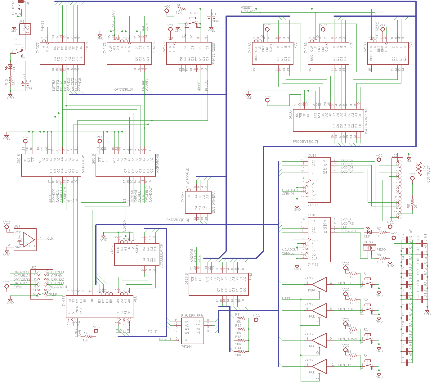
Schematics. I'm starting to make some progress with Eagle (light) and I'll be adding schematic diagrams of all of the circuits that make up my CPU. I just finished doing the 3rd Eagle layout of the program counter and this one actually makes sense to look at. The first two were a mess of wires intersecting and crossing over each other so that ...

16 Bit Cpu In Logisim Microprocessor Design In Logisim Digital Implementation Of 16 Bit Processor Logisim Circuit Of 16 Bit Cpu Multiple 16 Bit Bits Design
Custom 4-Bit CPU Schematic and Control. Enough with the vague design talk - here's the circuit schematic for the Nibbler 4-bit CPU! Click the image to zoom in to a full size view. The whole system fits on a single page, including the CPU itself and the I/O devices, so it's easy to wrap your head around. Except for RAM and ROM, all the ...
A circuit diagram is a visual display of an electrical circuit using either basic images of parts or industry standard symbols. Symbol usage depends on the audience viewing the diagram. These two different types of circuit diagrams are called pictorial (using basic images) or schematic style (using industry standard symbols).
I create tutorial-style videos about electronics, computer architecture, networking, and various other technical subjects.

0814 Printed Circuit Board Pcb With Chip Cpu Microprocessor With Connections For Eda Ppt Slides Templates Powerpoint Slides Ppt Presentation Backgrounds Backgrounds Presentation Themes
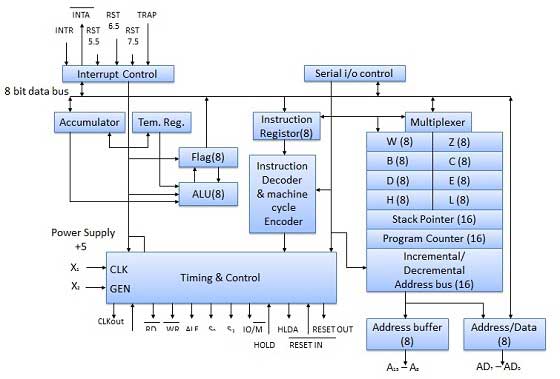
Major parts of a CPU []. Below we see a simplified diagram describing the overall architecture of a CPU. You must be able to outline the architecture of the central processing unit (CPU) and the functions of the arithmetic logic unit (ALU) and the control unit (CU) and the registers within the CPU.. Do I understand this, part one []
Cpu Microprocessor Microchip And Circuit Board Stock Vector Illustration Stock Vector Image Art Alamy
A central processing unit (CPU), also called a central processor, main processor or just processor, is the electronic circuitry that executes instructions comprising a computer program.The CPU performs basic arithmetic, logic, controlling, and input/output (I/O) operations specified by the instructions in the program. This contrasts with external components such as main memory and I/O ...
Z80 Schematic This is a system example with PARALLEL, SERIAL, RAM and ROM. Z80 Schematic (Protel) The schematic above in the original Protel format. 3 GIFs with Z80 Circuits Z80 CPU and Memory, CTC, SIO, and drivers for RS-232 interface. Z80 system circuit Z80 CPU with EPROM, RAM and PIO, by M.Kimura.
The name CPU 31x summarizes all standard CPUs, as table below shows: CPU Convention: CPU designations: Order number As of firmware version CPU 312 6ES7312-1AE14-0AB0 V3.3 CPU 314 6ES7314-1AG14-0AB0 V3.3 CPU 315-2 DP 6ES7315-2AH14-0AB0 V3.3 CPU 315-2 PN/DP 6ES7315-2EH14-0AB0 V3.2 CPU 317-2 DP 6ES7317-2AK14-0AB0 V3.3 ...
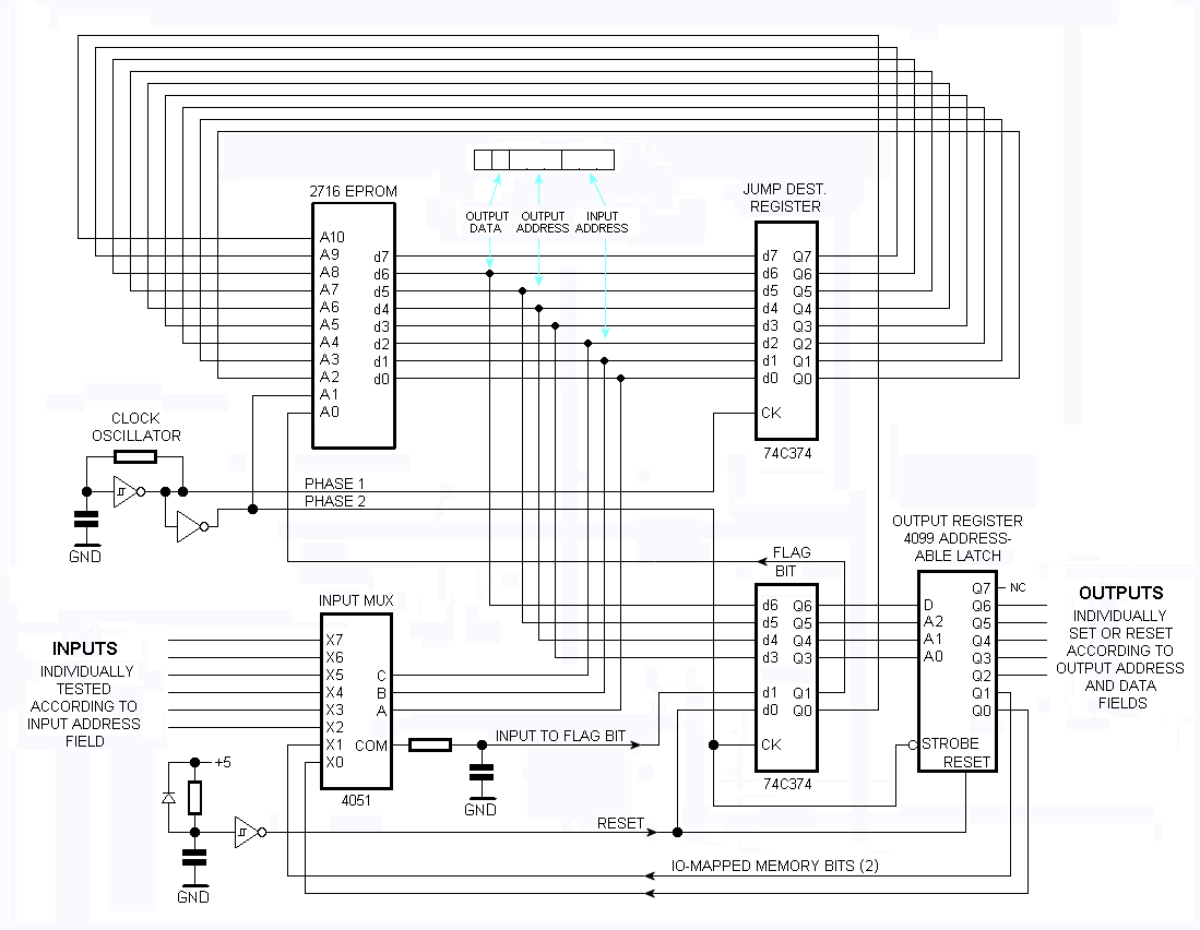
The tiny part of circuit in the OP seems pretty meaningless, it's not a 'simplified' processor, but merely a tiny part of one. For the OP - I would completely ignore the 'diagram', it's of no use to you (or anyone else), and presumably was only given to explain a small specific point.
This is a conceptual circuit diagram of the power train of a typical ATX computer power supply unit. This schematic does not show the control circuitry, that's why you see all MOSFET gates and transistor bases are open. For clarity, the parts responsible for miscellaneous auxiliary functions, such as current limit, fan control, and OV ...
The central processing unit (CPU) The CPU in modern computers is the embodiment of the "mill" in Babbage's difference engine. The term central processing unit originated way back in the mists of computer time when a single massive cabinet contained the circuitry required to interpret machine level program instructions and perform operations on ...
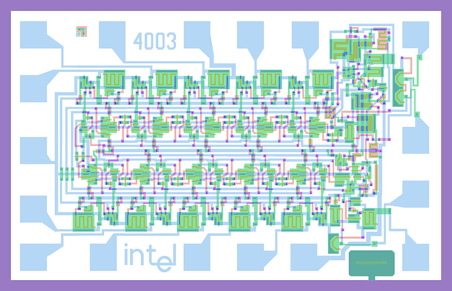
Intel 4004 Cpu 4 Bit Central Processing Unit Cpu Computer Chip Integrated Circuit Mask Digital Art By Kathy Anselmo













Comments
Post a Comment