39 700r4 transmission wiring diagram
Hi there, I'm brand new to the website, can you please clarify 1985 700R4 Lock-Up wiring diagram for me? I've seen various wiring diagrams for 3-prong connectors, I need to know which is correct and why. Guidance is much appreciated. Chev pin-A to 12V source via 10amp fuse/toggle switch... 700R4 Transmission Wiring Diagram 2018 700R4 Torque Converter Lockup - 700R4 Torque Converter Lockup Wiring Diagram. Wiring Diagram not merely offers comprehensive illustrations of whatever you can perform, but in addition the processes you need to follow although doing so.
June 1, 2020. 700r4 Transmission Wiring Schematic. – Welcome to be able to our website, in this period We’ll show you concerning 700r4 transmission wiring schematic. . And now, this is actually the first photograph: 700R4 TCC Wiring Diagram from 700r4 transmission wiring schematic , source:jalopyjournal.com. 700R4 TCC Wiring Diagram from ...

700r4 transmission wiring diagram
1. Connect the transmission connector plug to the transmission plug on the driver side and be sure it is plugged in securely. 2. Apply a 12V+ voltage to the loose pigtail of the connector plug. 3. (A)You should see a small spark when connecting and you will hear a faint "click" inside the transmission. This is an indicator you have a functioning, It was fed by the 1-2 shift valve. gov pressure would stroke the valve and it would feed oil to the .020 orifice in the stator, twix the lock-up valve and the lu solenoid. The unit did not need an ecm to ground the solenoid. The spring pressure staged the lock-up valve to stroke. Heavier the spring the later the lock-up. 700r4 Tcc Wiring Diagram. Need to wire up the TCC to the ECM. Being that the truck was Thread: and r4 TCC wiring This is the diagram for what I need. Here is a diagram from TCI I believe: Here is a diagram and a picture (several pics collaged together)of what found when I dropped my trans.
700r4 transmission wiring diagram. I put a 2004r in my 73 and installed the TCI wiring kit and it works great. The guy at the cruise said he was putting in a 700r4 and wanted to know if you really had to install the kit to make the tranny work in all 4 gears. Wiring Calibration (Electric Speedometer calibration made easy!) To calibrate your electric speedometer: 1. With the power off, push and hold the Trip/Reset button. While holding the button, start the vehicle and continue to hold the button until the pointer sweeps to full scale and stays at full scale. You may now release the button. 700r4 Speedometer Plug Wiring Diagram. Sep 16, Wiring AutoMeter electric speedometer to r4. Join us, it's free! I pulled a connector to plug into the trans from the pull-a-part salvage. This is a 2 wire The AAW harness has 1 ground-yellow wire & 1 signal-purple wire. An electrical speedometer reads pulses (signal) from the signal source. 700r4 Transmission Speed Sensor Wiring Diagram- wiring diagram is a simplified up to standard pictorial representation of an electrical circuit.It shows the components of the circuit as simplified shapes, and the capacity and signal links in the midst of the devices.
Jun 03, 2021 · For an example wiring diagram. 700r4 wiring submitted by markzz3 on your tranny you will have a 4 prong plug. The b m thr4 is a specially modified transmission intended. The b m th 700r4 is a specially modified transmission intended for performance and heavy duty applications. R4 torqe converter lock up wiring. hydraulic diagram for a 700R4 TV valve (figure 1). TV limit oil, indicated in orange, enters between lands 2 and 3. This pressure now becomes TV pres-sure, indicated in yellow on the diagram. TV oil gets routed through a small TV balance orifice to land 1. Balance oil pushes the TV valve to a position which blocks the feed from TV limit oil ... 700r4 wiring diagram - thanks for visiting my site, this post will certainly discuss concerning 700r4 wiring diagram. We have accumulated many photos, with any luck this picture is useful for you, as well as assist you in locating the solution you are trying to find. Description : 700R4 Tcc/lockup Wiring - The You are looking for 700r4 transmission overdrive wiring you’ve come to the right place. We have 9 diagram about 700r4 transmission overdrive wiring including images, pictures, photos, and more. You’ll likely find lots of different sample diagrams here. Such as png, jpg, animated gifs, pic art, logo, black and white, transparent, etc.
Technical 700r4 wiring. Discussion in 'The Hokey Ass Message Board' started by ohenry ... so we can't say without at least seeing a picture of the bottom of your transmission (with the pan and filter off, of course). ... You are going to be looking long and hard for that wiring diagram though. The 4.3 didn't come out until '88 in S10's ... Torque converter lockup on the 700R4 transmission is controlled by the TCC solenoid. When the solenoid is engaged, fluid is applied to the torque converter clutch, creating lockup and a direct link between the engine and transmission. This feature is often controlled by the vehicle's computer when certain ... Th 700r4 Tcc Lockup Wiring The 1947 Present Chevrolet Gmc Truck Message Board Network. Th 700r4 tcc lockup wiring the 1947 diagram h a m b simple ls1tech present chevrolet gmc truck message vacuum switch grabtop nl hot rod forum corvette discussion help ck5 network lock up controlled in 1984 1988 transmission pressure bangshift info page 1 th350 tci 376600 od chevy tri five wire 700 r4 harness ... wiring kit further 4l60e transmission wiring plug diagram on 700r4. Architectural wiring diagrams work the approximate locations and interconnections of receptacles, lighting, and remaining electrical facilities in a building. Interconnecting wire routes may be shown approximately, where particular receptacles or fixtures must be upon a common circuit.
This easy-to-install lockup wiring kit for 700R4 and 2004R transmissions from TCI® allows hands-free, automatic activation of the torque converter clutch in 4th gear under stable engine operation, and disengages the clutch when accelerating or down shifting. This universal lockup wiring kit is needed when installing a GM 700R4 or 2004R transmission in a non-computer controlled application ...
Using An Electronic Speedo With Tbi And 700r4 The 1947 Present Chevrolet Gmc Truck Message Board Network
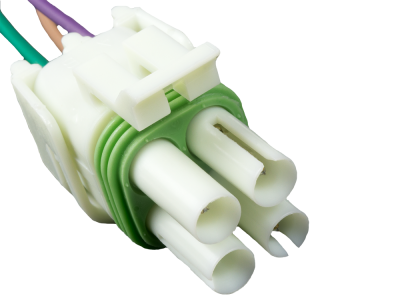
I just put a 700R4 out of an 88 chevy truck into my 73 Chevy and was trying to wire the TCC but the wires on my harness coming out of the trans connector are Light Blue, Purple and a Tan with black stripe. According to my wiring diagram the Light blue goes from the High gear in on the ECM and...
700r4 Transmission Wiring Diagram Hecho Diagram Data Schema Exp 42re Wiring Diagram Wiring Diagram Transmission Valve Body Diagram In Addition Saturn Transmission 4l80e Transmission Parts Diagram Inspirational Sonnax Gm 4l80 E Share this post. 0 Response to "700r4 Transmission Parts Diagram"
Apr 21, 2019 · on 700r4 Transmission Lock Up Wiring Diagram. How to wire your R4 to lockup in fourth gear without a computer. With an overdrive transmission and hp, fuel economy exceeding 20 mpg can be a. R4 Torqe Converter Lock Up Wiring. Malcolm Now I will have a back up automatic transmission built and ready to install.
I've learned a lot over the winter rebuilding my Chevy automatic transmissions. Thanks a bunch to Michelle for letting me take over the basement all winter ...
If such a flow sheet or diagram does not exist it might be helpful for one the trans gurus to create one. 86 Chevy suburban 6.2 + 700r4 K+N air cleaner, Dual 2 1/2 inch exhaust, twin Optima red tops, Lucas fuel additive used in nearly every tank since new , its a 4x4 with 250,000 miles no rebuild still runs great! Save.
Some 700R4 transmission do not have this auxiliary valve body but came with a small support plate. If you have this type of 700R4 transmission, remove the four bolts holding the small support plate to the case at the rear of the valve body. Remove the two valve body bolts holding the throttle pressure mechanism. Disengage the wire cable linkage ...

Just Installed A 700r4 Transmission On My 66 Impala Previously With A Powerglide And Need Some Help R Cartalk
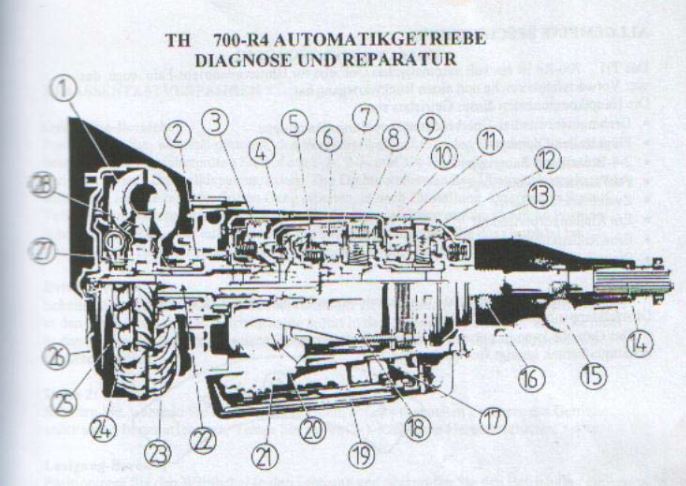
In summary, the 700r4 transmission was a 4-geared hydraulic automatic transmission with the 4th gear, an overdrive gear (30% increase). The transmission was made between 1982-1992. It had a case length of 23.5″~ and a weight of 170 lbs~ without fluid inside it.
External wiring from the oil pressure switch at the transmission leads to a dash switch and on to REAL WORLD WIRING DIAGRAM. The fuse holders 4. (B) If it now clicks, you have a 2 wire solenoid and must ground the lead permanently.Oct 19, · The subsequent charts provide precise sender resistance values for three specific gauge readings (Low ...
700R4 Lockup Wiring Diagram – 700r4 4th gear lockup wiring diagram, 700r4 converter lockup wiring diagram, 700r4 lockup kit wiring diagram, Every electric arrangement consists of various diverse pieces. Each component ought to be set and connected with other parts in specific way. If not, the structure won’t function as it should be.
Unique Of 700R4 Transmission Lock Up Wiring Diagram Simple - 700R4 Lockup Wiring Diagram. Additionally, Wiring Diagram provides you with the time frame by which the assignments are for being finished. You will be in a position to understand precisely if the tasks ought to be finished, that makes it much easier to suit your needs to properly ...
The B&M TH-700R4 is a specially modified transmission intended for performance and heavy duty applications. It is suitable for use behind engines producing up to 450 lb- ... for an example wiring diagram. The second approach is to install a speed sensing device (such as B&M P/N 70244 or 70248) ...
700r4 Tcc Wiring Diagram. Need to wire up the TCC to the ECM. Being that the truck was Thread: and r4 TCC wiring This is the diagram for what I need. Here is a diagram from TCI I believe: Here is a diagram and a picture (several pics collaged together)of what found when I dropped my trans.
It was fed by the 1-2 shift valve. gov pressure would stroke the valve and it would feed oil to the .020 orifice in the stator, twix the lock-up valve and the lu solenoid. The unit did not need an ecm to ground the solenoid. The spring pressure staged the lock-up valve to stroke. Heavier the spring the later the lock-up.
1. Connect the transmission connector plug to the transmission plug on the driver side and be sure it is plugged in securely. 2. Apply a 12V+ voltage to the loose pigtail of the connector plug. 3. (A)You should see a small spark when connecting and you will hear a faint "click" inside the transmission. This is an indicator you have a functioning,







Comments
Post a Comment